NOTE: Depending on the voltage of the DC feeds, power can be drawn from both feeds. The
feed with higher voltage provides more power. If the difference between the voltages is sufficient,
then the higher voltage feed provides all the power. When the voltages are exactly the same,
equal power is drawn from both feeds.
These feeds are set by the input mode DIP switch located on the DC PSM (see “MX2020DC Power Supply
Module (-48 V) Description” on page 112). Each set of power cables powers a single DC PSM and is capable
of delivering 2500 W of power if 80 A feeds are connected. If feeds that connect to one PDM fail in a
redundant configuration, the other feed provides full power .
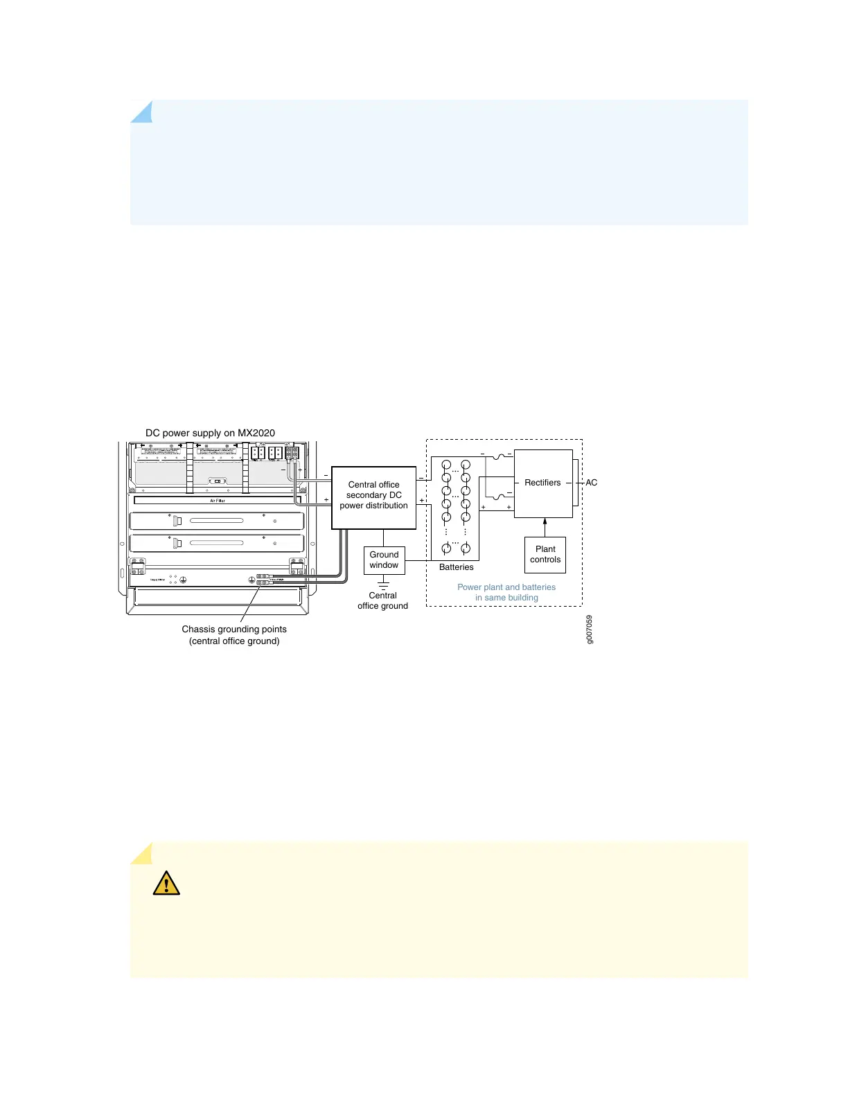
Figure 74 on page 202 shows a typical DC source cabling arrangement.
Figure 74: Typical DC Source Cabling to the Router
g007059
AC
Plant
controls
Rectifiers
Power plant and batteries
in same building
Batteries
DC power supply on MX2020
Ground
window
Central
office ground
Chassis grounding points
(central office ground)
Central office
secondary DC
power distribution
All DC PSMs in a subsystem share the load (nine PSMs on the top half share the load, as well as the nine
PSMs on the bottom share the load). If one PSM fails in a redundant configuration, the remaining PSMs
provide power to FRUs. Up to eighteen PSMs may be required to supply power to a fully configured router.
Nine PSMs in the lower card cage supply power to the two CB-REs (active and redundant), eight SFBs,
lower ten MPCs, two lower fan trays and one fan tray on the top half. Nine PSMs in the upper card cage
supply power to the two upper fan trays, upper ten MPCs, two CB-REs (active and redundant), eight SFBs,
and a fan tray in the lower card cage. A portion of power from each zone is reserved to power critical
FRUs. These FRUs allow the system to operate even if power to a complete zone fails.
CAUTION: You must ensure that power connections maintain the proper polarity.
The power source cables might be labeled (+) and (-) to indicate their polarity. There
is no standard color coding for DC power cables. The color coding used by the external
DC power source at your site determines the color coding for the leads on the power
cables that attach to the terminal studs on each PDM.
202