Table 75: MX2020 DC Power Zoning (Base DC Power Implementations)
Components Receiving
Power
Power Supply
Module (PSM)
Power
Distribution
Module (PDM)Power Zone
Chassis Power
Configuration
•
MPC slots 0 through 9
•
Fan Tray 1
PSM slots 0
through 8
PDM 0 and 1Lower (zone 0)DC power to lower
half of MX2020
components
•
MPC slots 10 through
19
•
Fan Tray 3
PSM slots 9
through 17
PDM 2 and 3Upper (zone 1)DC power to upper
half of MX2020
components
•
CB-RE slot 0 and slot 1
•
SFB slots 0 through 7
•
Fan tray 0 and 2
Zone 0 + Zone 1
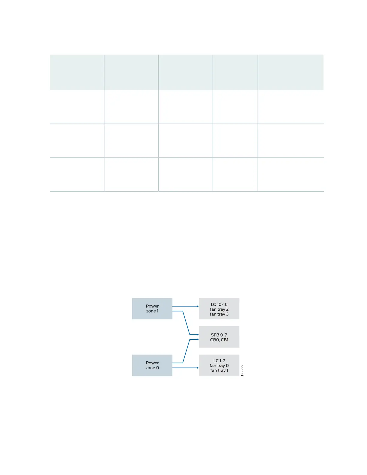
As illustrated in Figure 77 on page 211 and described in Table 76 on page 212, the power zones in MX2020
DC optimized power subsystems distribute power to FRUs as follows:
•
Zone 0 powers only line card slots 1-7, and fan trays 0 and 1
•
Zone 1 powers only line card slots 10-16, and fan trays 2 and 3
•
Zone 0 and Zone 1 (both zones provide power) to CB-RE slot 0 and CB-RE slot 1, and fabric card slots
0-7
Figure 77: Power Distribution in an Optimized DC Power Subsystem
211