2N8/2N7
1-4-200
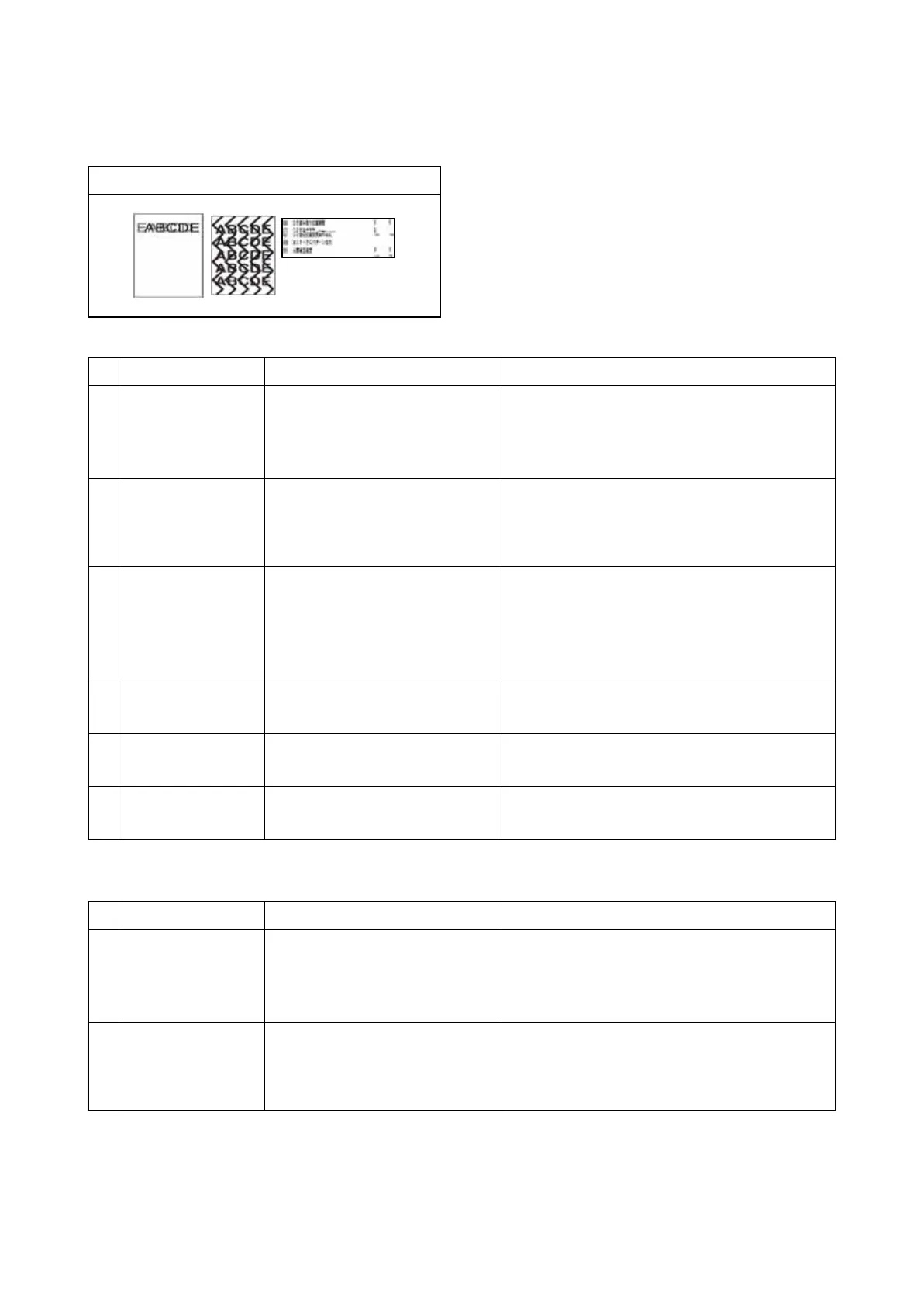
(17) Abnormal image
1. Table scanning
2. DP-scanning first (front) page
Print example
Defective part Check description Corrective Action
1
FFC cable CCD Check the FFC cable between
the CCD sensor and ISC PWB is
properly connected. Or, verify
conduction of the wire.
Reinsert the connector if its connection is
loose. Or, if conduction is lot, replace the wire.
2
SATA cable ISC
Check the SATA cable between
the ISC PWB and main PWB is
properly connected. Or, verify
conduction of the wire.
Reinsert the connector if its connection is
loose. Or, if conduction is lot, replace the wire.
3
HDD Check the wires to the HDD in
conduction. Check the connector
for connection. Check the con-
nector pins for distortion.
1. Reinsert the connector if its connection is
loose.
2. Check the wires and connetctors, and
replace if faulty.
3. Replace the HDD or the SATA wire.
4
ISC PWB The ISC PWB is defective. Replace the ISC PWB and perform U411.
(see page 1-3-152)
5
CCD PWB The CCD PWB is defective. Replace the ISU and perform U411.
(see page 1-3-152)
6
Main PWB The main PWB is defective. Replace the main PWB.(see page 1-5-74)
Defective part Check description Corrective Action
1
FFC cable CCD Check the FFC cable between
the CCD sensor and ISC PWB is
properly connected. Or, verify
conduction of the wire.
Reinsert the connector if its connection is
loose. Or, if conduction is lot, replace the wire.
2
SATA cable ISC
Check the SATA cable between
the ISC PWB and main PWB is
properly connected. Or, verify
conduction of the wire.
Reinsert the connector if its connection is
loose. Or, if conduction is lot, replace the wire.