2N8/2N7
1-5-122
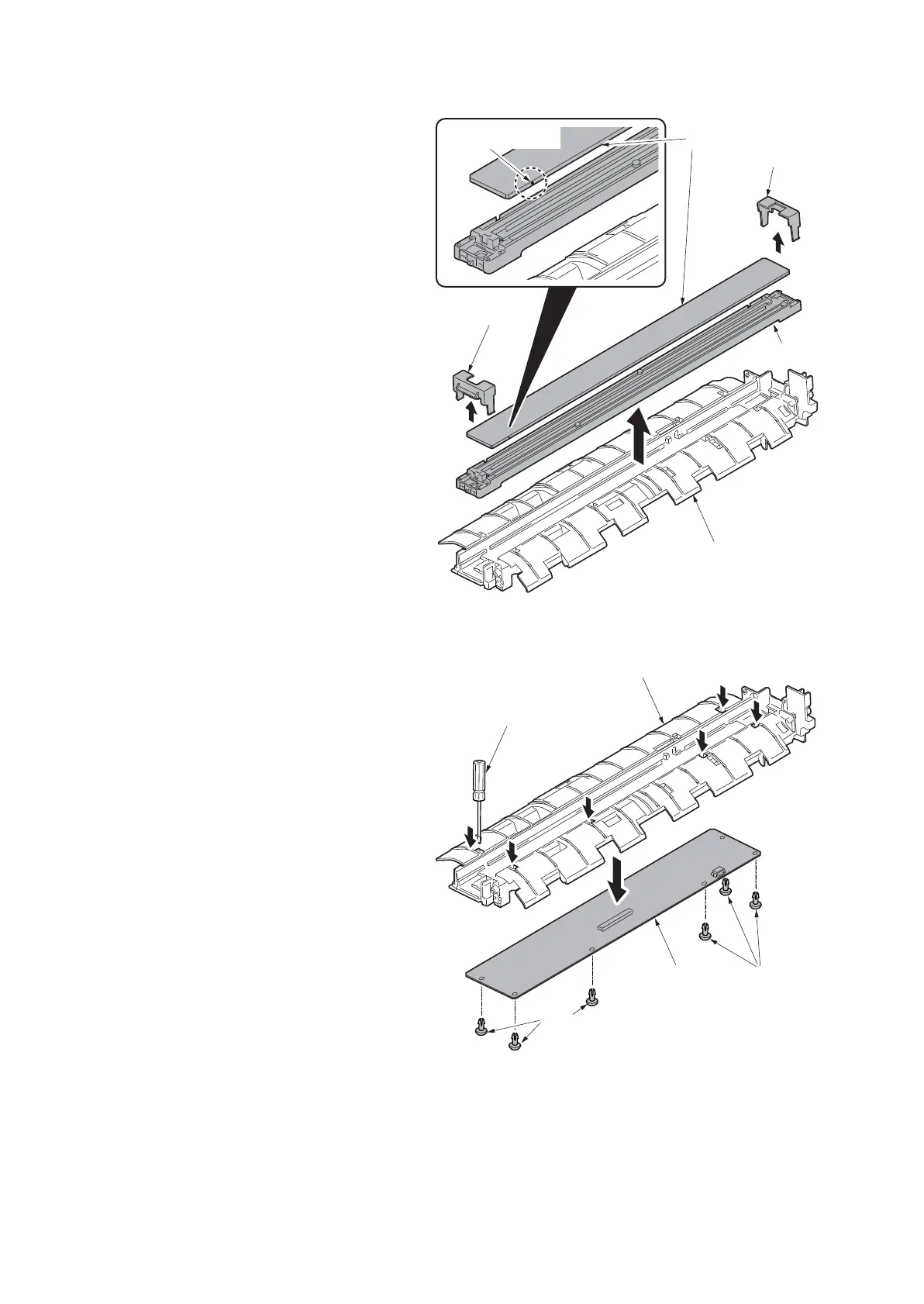
8. Remove the CIS front holder and CIS
rear holder and then remove the CIS slit
glass and CIS upwards.
*: Keep the CIS sensor away from dusts
and smears as it is exposed to the air
when the CIS slit glass has been
removed.
The sensor action will be deteriorated if
dusts and smears are adhered to it.
Figure 1-5-201
9. Remove six pins by using a flat screw-
driver and then remove the DPSHD
PWB.
10. Replace the CIS and refit all the
removed parts.
*: Observe the front and back side of the
CIS slit glass when the glass is
replaced.
*: Note the marking in the figure.
The sensor action will be deteriorated if
the slit glass is mounted upside down.
11. When the CIS is replaced with a new
one, carry out the following procedure.
12. Clean the CIS roller and contact glass
(CIS).
13. Perform maintenance mode U091 (set-
ting the white line correction) (see page
1-3-65).
Figure 1-5-202
14. Make a test copy of a gray document.
If problems such as white lines appear on the test copy, repeat the procedure from steps 15 and 16
onwards until the white lines no longer appear.
15. Perform maintenance mode U411 (Adjusting the scanner automatically) (see page 1-3-152).
Marking(Black)
CIS rear holder
CIS guide
CIS
CIS front holder
CIS slit glass
DP SHD PWB
CIS guide
Flat screwdriver
Pin
Pin







 To Next Page