2N8/2N7
2-3-29
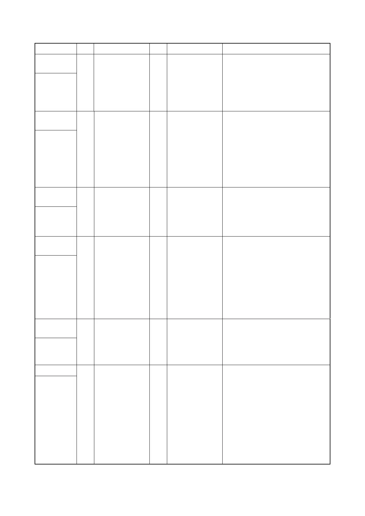
Connector Pin Signal I/O Voltage Description
TB
1 LIVE I 120 V AC
220-240 V AC
AC power input
Connected to
AC inlet and
main power
switch
2 NEUTRAL I 120 V AC
220-240 V AC
AC power input
5 DH_LIVE I 120 V AC
220-240 V AC
AC power input
YC1
1 LIVE_IN I 120 V AC
220-240 V AC
AC power output from MSW
Connected to
main power
switch
2 LIVE_OUT O 120 V AC
220-240 V AC
AC power output to MSW
3 NEUTRAL_OUT O 120 V AC
220-240 V AC
AC power output to MSW
4 NEUTRAL_IN I 120 V AC
220-240 V AC
AC power output from MSW
YC3
1 LIVE O 120 V AC
220-240 V AC
AC power output to FIHPWB
Connected to
fuser IH PWB
2 NEUTRAL O 120 V AC
220-240 V AC
AC power output to FIHPWB
YC8
1 DH_LIVE O 120 V AC
220-240 V AC
AC power output to CH
Connected to
cassette
heater
2 DH_LIVE - - Not used
3 NC - - Not used
4 NC - - Not used
5 DH_NEUTRAL O 120 V AC
220-240 V AC
AC power output to CH
6 DH_NEUTRAL - - Not used
YC9
1 DH_LIVE O 120 V AC
220-240 V AC
AC power output to PFCH
Connected to
large capac-
ity feeder
3 DH_NEUTRAL O 120 V AC
220-240 V AC
AC power output to PFCH
YC12
1 +24V1 O 24 V DC 24 V DC power to FPWB1
Connected to
feed PWB 1
2 +24V1 O 24 V DC 24 V DC power to FPWB1
3 +24V1 O 24 V DC 24 V DC power to FPWB1
4 5V1 O 5 V DC 5 V DC power to FPWB1
5 GND - - Ground
6 GND - - Ground
7 GND - - Ground
8 GND - - Ground







 To Next Page