2-58 Service Manual
7525-63x
6
Check the option cable connected to JOPT1
for continuity.
Is there continuity?
Go to step 8. Go to step 7.
7
Replace the cable and print from both option
trays.
Did the pages print from both trays?
Problem resolved. Go to step 8.
8
Print a menu settings page.
Are all the attached option trays listed on
the first page of the menu settings pages?
Note: If two option trays are used, the 650
sheet will appear as tray 2, and the 550
sheet tray will appear as tray 3.
Go to step 9. If the 550-sheet option failed
to appear, got step 9.
If the 650-sheet tray failed to
appear, go to step 10.
9
Remove the 650 sheet tray from the printer,
attach the 550 sheet tray directly to the printer,
and print a page from the 550 sheet tray.
Did the page print?
Go to step 11. Replace the 550-sheet tray.
10
With only the 650 sheet tray attached to the
printer, print a page from the 650 sheet tray.
Did the page print?
Go to step 11. Replace the 650-sheet tray.
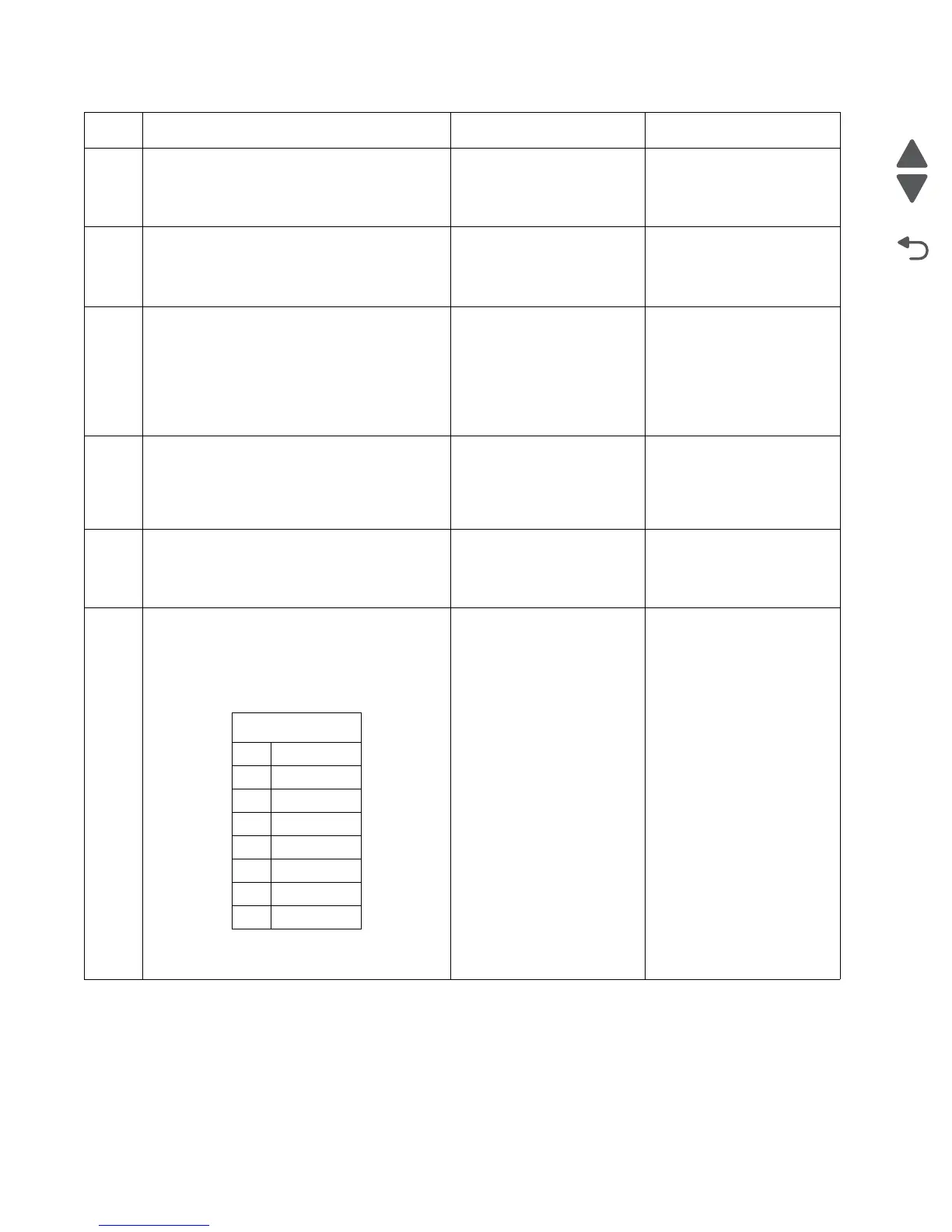
11
Turn off the printer, and remove the rear
shield. “Rear shield removal” on page 4-7.
Disconnect the cable at JOPT1 on the RIP
board. Turn the printer on, and measure the
voltages below.
Are the voltages correct?
Consult your next level
support.
Replace the RIP board. See
“RIP board removal” on
page 4-19.
Step Questions / actions Yes No
JOPT1
Pin Voltage
2 Ground
3 Ground
5+24 V
6 Ground
7+5 V
9 Ground
10 Ground
 Loading...