4-68 Service Manual
7525-63x
Toner patch sensor (TPS)—left and right removal
The toner patch sensors are similar, but the left sensor includes an extra cable and sensing device. Remove
them the same way.
1. Remove the ITU. See “Image transfer unit (ITU) removal” on page 4-43.
2. Remove the rear shield. See “Rear shield removal” on page 4-7.
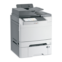
3. Disconnect the toner density sensor cable from JTDS1 connector (A Right) or JTDS2 connector (A Left) on
the RIP board. If you are removing the left toner density sensor, also disconnect the thermistor from
JFUSES1 connector (B) on the RIP board.
Note: Observe the cable routing for reinstallation.
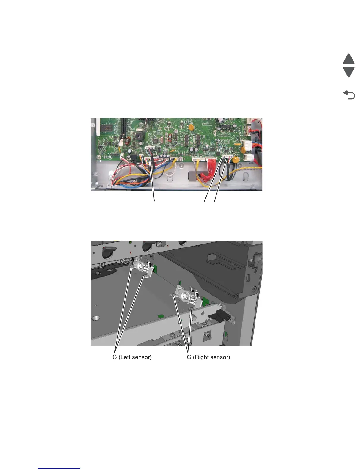
4. Remove the two screws (C) securing the sensors.
Note: Observe the cable routing for reinstallation.
A (Right sensor)
A (Left sensor)
B
 Loading...