4-72 Service Manual
7525-63x
4. Remove the backing from the new plate, and place the plate on the surface between the sensor mounting
posts.
5. Connect the cable to the tray present sensor.
6. Replace the spring.
USB connector removal
1. Remove the rear shield. See “Rear shield removal” on page 4-7.
2. Disconnect the USB connector from the RIP board.
3. Remove the flatbed assembly. See “Flatbed removal” on page 4-75.
Note: Do not remove the flatbed covers, or any of the hinges. The flatbed needs to be removed from the
print engine only.
4. Remove the operator panel from the flatbed assembly. See “Operator panel assembly removal” on
page 4-102.
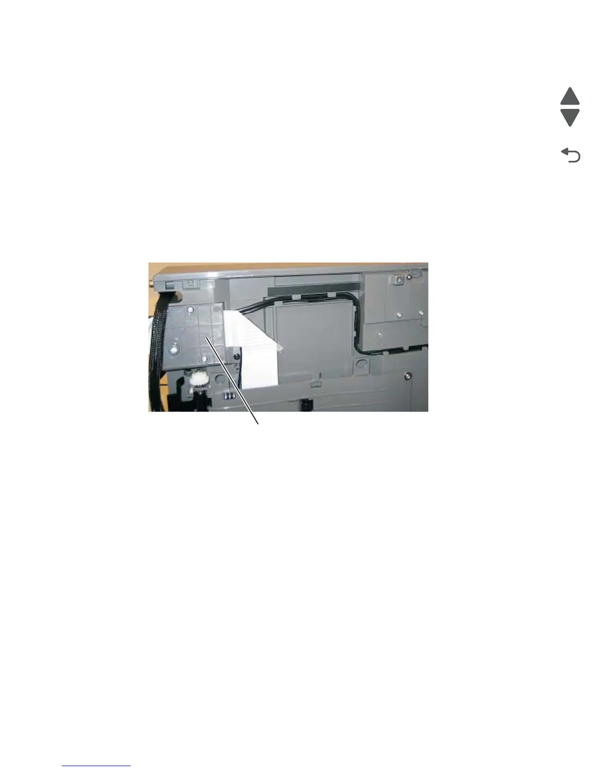
5. Remove the CCD ribbon cable cover (A), and route the USB cable out through the cable channel on the
flatbed unit.
 Loading...