Diagnostic information 2-35
7525-63x
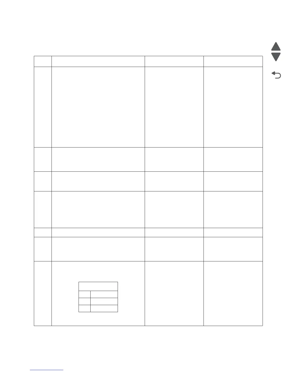
Duplex/manual feed sensor (S1) service check
Note: Before performing this service check, ensure that the printer is on a hard level surface.
Step Questions / actions Yes No
1 Enter the Diagnostics Menu.
1. Turn off the printer.
2. Press and hold 3 and 6.
3. Turn on the printer.
4. Release the buttons when the progress bar
appears.
Perform the Base Sensor Test. See “BASE
SENSOR TEST” on page 3-20.
1. Navigate to BASE SENSOR TEST >
Input - S1.
2. Install Tray 1.
Does the display indicate
Input - S1: Media Clear?
Go to step 2. Go to step 4.
2
Pull Tray 1 out.
Does the display indicate
Input - S1: Media Present?
The sensor is functioning
correctly.
Go to step 3.
3
Remove the tray, and inspect sensor.
Is there something obstructing the sensor?
Remove the obstruction and
restart the test.
Go to step 4.
4
Inspect the spring-loaded shaft/flag in the tray.
The flag portion of the shaft intercepts the
sensor, except when a sheet is being staged
for duplexing.
Does the shaft rotate freely and return to
home position (flag at top of rotation)?
Go to step 5. Replace the tray with a new
one.
5
Is the flag on the shaft broken? Replace the tray. Go to step 6.
6
Is the cable correctly connected to JFUSES1
on the RIP board and to the sensor.
Is the sensor cable properly connected?
Go to step 7. Reconnect the cable.
If the problem persists, go to
step 7.
7
Turn the printer off, and remove the rear
shield. See “Rear shield removal” on
page 4-7. Turn the printer on, and check the
values at JFUSES1:
Are the values approximately correct?
Replace the duplex sensor.
See “Duplex sensor
removal” on page 4-29.
Replace the RIP board. See
“RIP board removal” on
page 4-19.
JFUSES1
Pin Value
8 Ground
9 +3.3 V dc
 Loading...