Diagnostic information 2-41
7525-63x
Operator panel service checks
Warning: Replace one of the following components, and perform a POR before replacing a second component.
Never replace both of the components without performing a POR after installing each one, or the
printer will be rendered inoperable:
• Operator panel assembly
• RIP board
Warning: Never install and remove components listed above as a method of troubleshooting components.
Once a component has been installed in a printer, and the printer is powered on, it cannot be
used in another printer. It must be returned to the manufacturer.
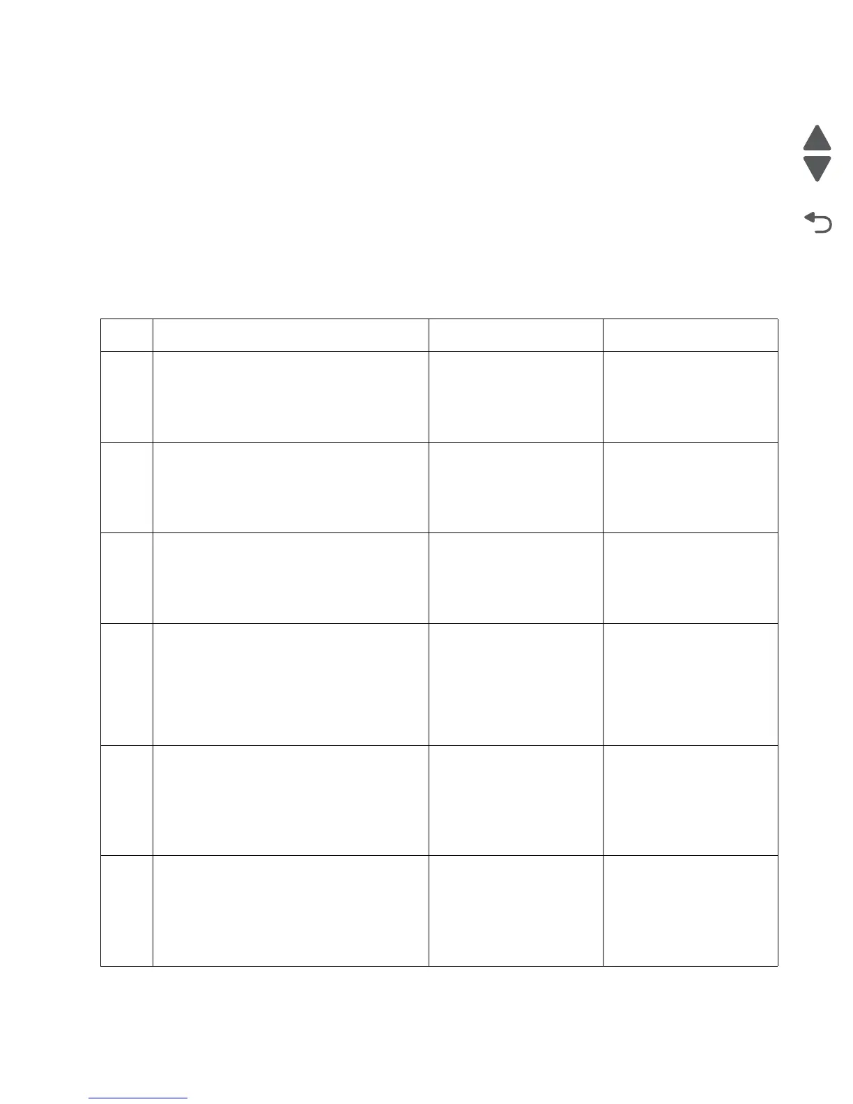
One or more operator panel buttons fail
Step Questions / actions Yes No
1 Check the cable connection between the RIP
and the UICC, and check the connection from
the UICC to the display.
Are the cables properly connected?
Go to step 3. Go to step 2.
2
Reconnect the cables. POR the device into
Diagnostics mode, and perform the button test.
See “Button Test” on page 3-17.
Do any of the buttons fail the test?
Go to step 3. Problem resolved.
3
Using a multimeter, check the cable
connecting operator panel to the RIP board for
continuity.
Is there continuity?
Go to step 5. Go to step 4.
4
Replace the UICC cable. See “User interface
controller card cable removal” on
page 4-112.
POR the device into Diagnostics mode, and
perform the button test.
Do any of the buttons fail the test?
Go to step 5. Problem resolved.
5
Replace the UICC. See “User interface
controller card removal” on page 4-113.
POR the MFP into Diagnostics mode, and
perform the button test.
Do any of the buttons fail the test?
Go to step 6. Problem resolved.
6
Replace the RIP board. See “RIP board
removal” on page 4-19.
POR the device into Diagnostics mode, and
perform the button test.
Do any of the buttons fail the test?
Contact your next level of
support.
Problem resolved.
 Loading...