2-62 Service Manual
7525-63x
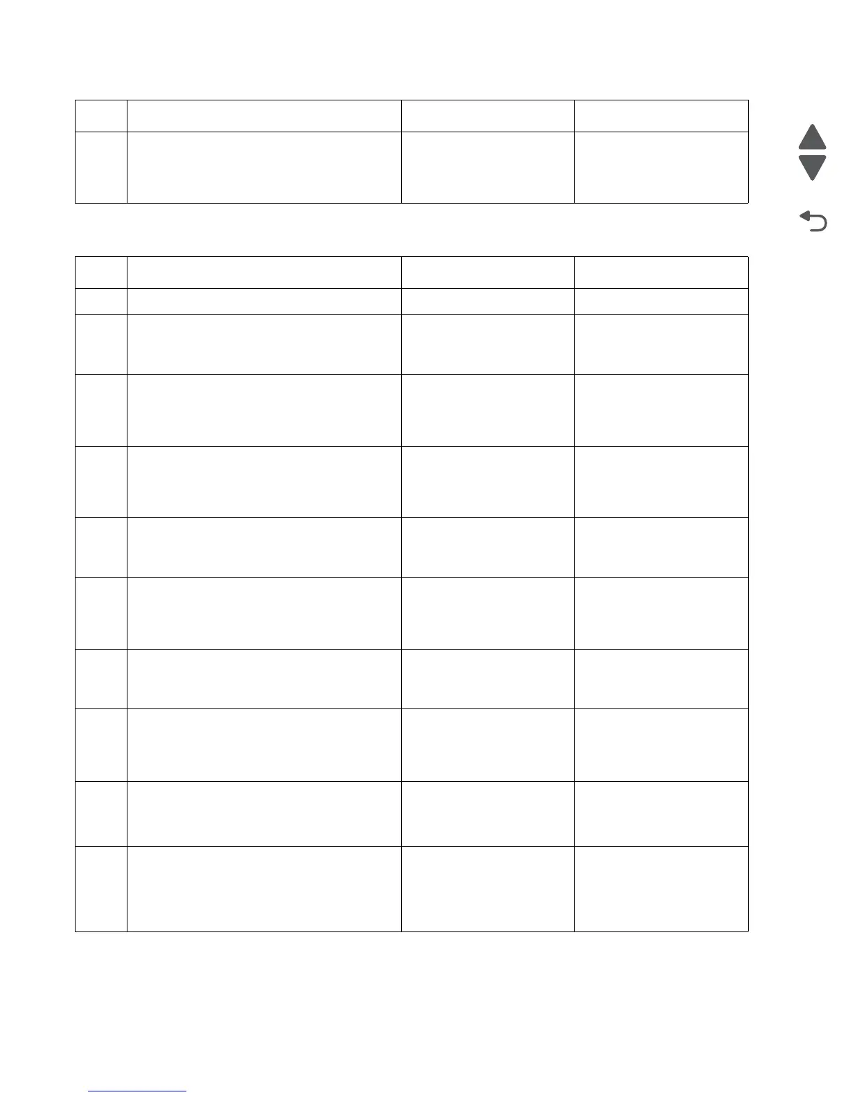
ADF cover open service check
6
Check pin 1 in JHS1 for voltage. The voltage
should measure +5 V dc. pin 2 should be GND.
Is voltage present and is it correct?
Replace the flatbed unit.
See “Flatbed removal” on
page 4-75.
Replace the RIP board. Go
to “RIP board removal” on
page 4-19.
Step Questions / actions Yes No
1 Is the ADF cover properly closed? Go to step 3. Go to step 2.
2
Close the ADF cover.
Does the problem go away?
Issue resolved Go to step 3.
3
Perform the ADF cover open sensor test. Go to
“SCANNER TESTS” on page 3-26.
Does the sensor work properly.
Go to step 4 Go to step 8.
4
On the bottom of the ADF cover, inspect the
ADF cover closed sensor actuator.
Does it move freely?
Go to step 6. Go to step 5.
5
Fix the actuator so it moves freely.
Did this fix the problem?
Problem resolved. Go to step 6.
6
Remove the ADF rear cover and inspect the
ADF cover closed sensor for dirt and debris.
Are there dirt and debris present?
Go to step 7. Go to step 8.
7
Clean the dirt and debris from the sensor.
Did this fix the problem?
Problem resolved. Go to step 8.
8
Inspect the connections on the ADF relay card
in the ADF.
Are they properly connected?
Go to step 9. Secure all the connections.
9
Check the ADF cable for continuity.
Is there continuity?
Go to step 10. Replace the ADF cable. See
“ADF cable removal” on
page 4-89.
10
Check for signals or voltages from JADF1 on
the RIP board. Pins 11 and 12 should measure
+24VDC. Pin 5 should measure +14VDC.
Are there signals or voltages present?
Replace the ADF. See
“Duplex ADF removal” on
page 4-87.
Replace the RIP board. See
“RIP board removal” on
page 4-19.
Step Questions / actions Yes No
 Loading...