Gocator Line Profile Sensors: User Manual
Gocator Web Interface • 144
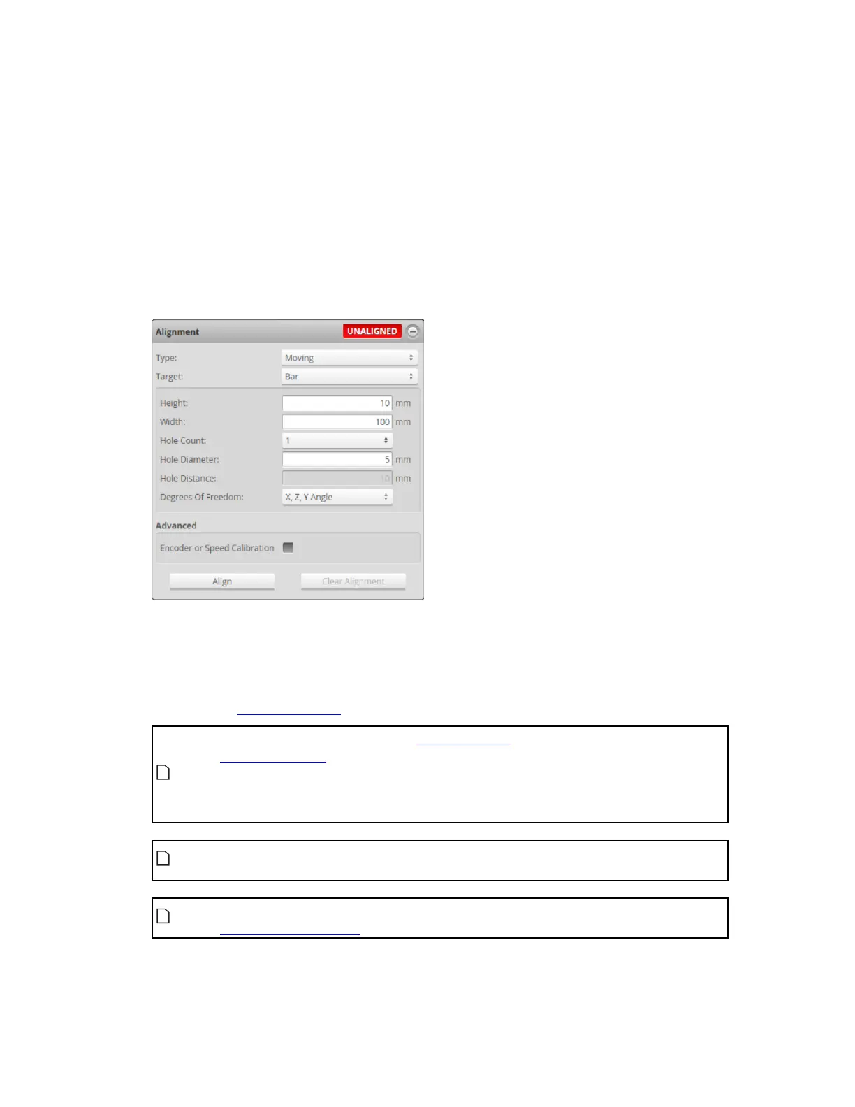
2. In the Alignment panel, select Moving as the Type.
3. Clear the previous alignment if present.
Press the Clear Alignment button to remove an existing alignment.
4. Select an alignment Target.
l Select one of the disk Disk options to use a disk as the alignment reference.
l Select Bar to use a custom calibration bar.
Configure the characteristics of the target (bar dimensions and reference hole layout); for details
on alignment bars, see Alignment Targets on page 28.
Degrees of Freedom: In moving bar alignment, three options are available, which are
combinations of different types of alignments. X, Y, and Z compensate for offsets on the X, Y, and Z
axes, respectively. YAngle and ZAngle compensate for rotation around the Yand Zaxes,
respectively. Compensating for Xangle rotation is currently only possible by manually setting the
rotation in the Transformations panel.
The Y offset, X angle, and Z angle transformations cannot be non-zero when
Uniform Spacing is unchecked. Therefore, when aligning a sensor using a bar
alignment target with Uniform Spacing unchecked, set the Degrees of Freedom
setting to X, Z, Y Angle, which prevents these transformations from being non-
zero.
On sensors aligned using Z angle or X angle, and to a lesser extent Y offset, CPU
usage increases when scanning, which reduces the maximum scan speed.
Artifacts may appear in scan data on sensors aligned using Z angle or X angle if
encoder trigger spacing is set too high (resulting in a low sampling rate).
 Loading...

