5-12 Calibration and Adjustment
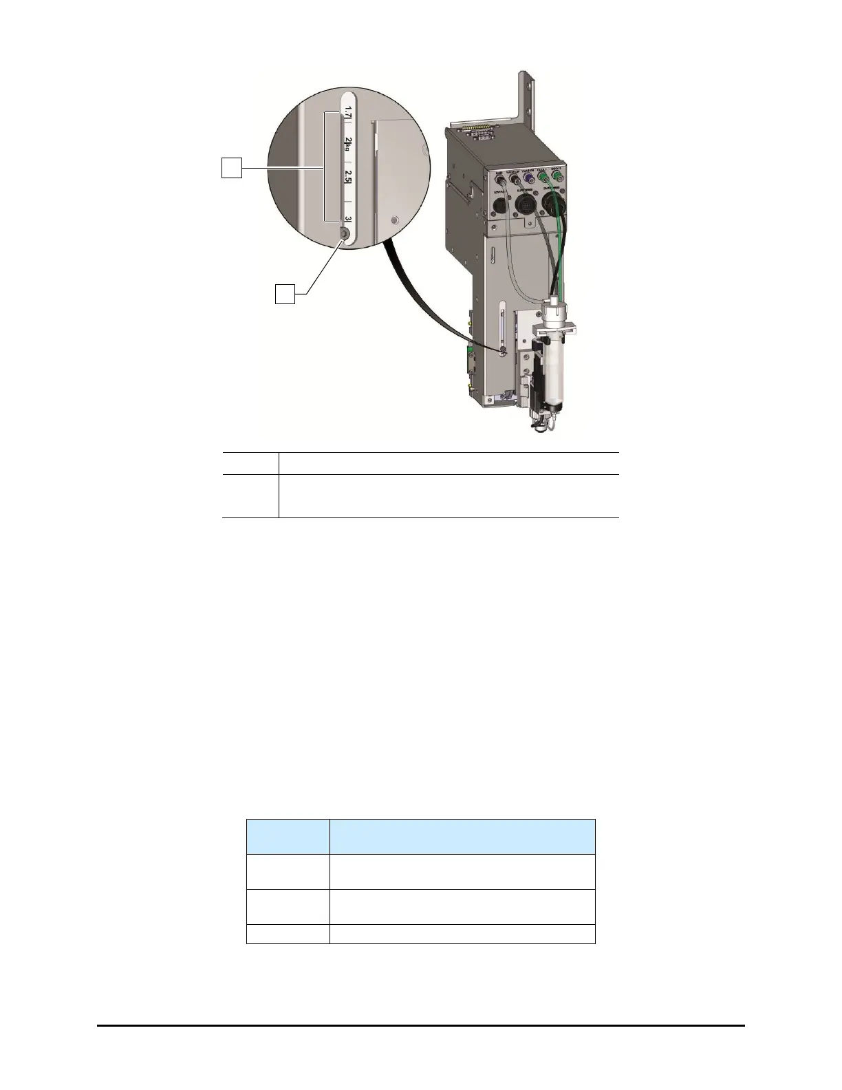
1 Payload Settings
2 Adjustment Screw
Figure 5-13 Z-Head Counterbalance Force Adjustment
7. Reinstall the camera and bracket.
8. Reconnect the camera and light source cables.
9. Recalibrate the camera. See 5.6 Calibrating the Camera.
10. Perform a machine offsets procedure. See 4.9 Valve Offsets.
To test counterbalance tension:
1. Place valve on Z-head and move it to middle of dispense area.
2. Open the dispensing system hatch.
The Z-head should not rise or drop more the 6.3 mm (1/4 inch).
3. Readjust tension if necessary.
Table 5-1 Counterbalance Spring Settings
Typical Applications
0 - 1.7
Standard (i.e. single valve)
Standard with laser height sensor
1.7 - 2.2
Dual action
Dual action with laser height sensor
Any custom tooling exceeding 2.2-kg
NOTE The settings in Table 5-1 are for reference purposes only. Certain applications may
require different settings.

 Loading...


