4-12 Operation
4.7.1 Dispenser Jog Controls
1. Click on the Dispenser Radio button to activate the dispensing head jog controls.
2. Dispensing head jog controls (Figure 4-12) operate as follows:
On the X-Y control panel, the arrows pointing to the Left move the dispensing head to
the left and the arrows pointing to the Right move it to the right.
On the X-Y control panel, the arrows pointing Up move the dispensing head toward the
back of the dispensing area and the arrows pointing Down move it toward the front of
the dispensing area.
On the Z-axis control panel, the arrows pointing Up move the dispensing head upward
and the arrows pointing Down move it downward.
Clicking on a Locations button, sends the dispensing head to a pre-defined location, i.e.
purge station, scale station.
The “white circles/dots” in the Target Box represent system locations that have been
previously taught.
Clicking on
Home sends the dispensing head to its home position. The home position is
the extreme left front corner of the dispensing area, where the Dispensing Head X, Y,
Z-axes coordinates are set to (0, 0, 0).
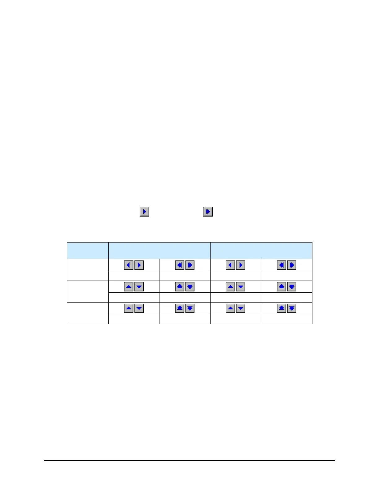
NOTE The single arrows and double arrows
move the dispensing head different
distances and different velocities per mouse click. See Table 4-1.
Table 4-1 Dispensing Head Jog Controls: Jog Distance and Velocity
(1)
Movement
Distance
(2)
Velocity
X
0.0254 (0.001) 2.54 (0.100) 1.27 (0.050) 88.9 (3.500)
Y
0.0254 (0.001) 2.54 (0.100) 1.27 (0.050) 88.9 (3.500)
Z
0.0254 (0.001) 1.27 (0.050) 2.54 (0.100) 10.16 (0.400)
Notes: (1) Default distances and velocities. Refer to the Fluidmove User Guide or Online
Help to modify jog distances and velocities.
(2) Distance per mouse click on the arrow button.

 Loading...


