Calibration and Adjustment 5-15
5.11 Adjusting the Board Sensors
Board Sensors are optical sensors located along the length of the front conveyor rail. The sensors detect
the presence of the workpiece and report it to the Conveyor Controller. Board sensor sensitivity should be
adjusted after initial installation and if the sensors fail to sense the presence of a workpiece. Depending on
whether the system has a single-lane or dual-lane conveyers, there may be as many as six downward-
facing board sensors (pre-dispense, dispense, and post-dispense station for each conveyor). Sensitivity
adjustments for downward-facing board sensors are made on Fiber Optic Amplifiers mounted under the
dispensing area front cover.
5.11.1 Standard Operation and Tuning
To install the board sensor:
1. Unlock the fiber lock (UP position). Insert ferrule ends until the fiber cords are fully seated.
Lock the fiber lock down into position on the conveyor rail (Figure 5-16).
NOTE Fiber ends are not designated as send or receive. Each ferrule can be used in
either amplifier position.
2. Verify that the digital value of the amplifier is less than 100 with the fiber array pointed
away from any objects (within 6 inches). This ensures array “cross-talk” will not
significantly degrade the signal.
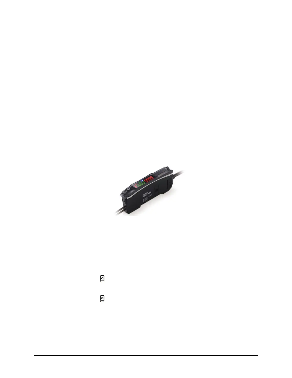
Figure 5-16 E3X-HD Board Sensor
To adjust for workpiece presence/absence (Figure 5-17):
NOTE The E3X-HD 11 sensor requires only one button; place the part/board over the sensor and
push
STune and then move the part/board away from the sensor and push STune again
(see below).
1. With the machine on and the fiber installed into the amplifier, place the carrier/board on the
conveyor so that it is breaking the fiber optic sensor beam.
2. Press the
STune button once.
3. Move the carrier/board so that it is clear of the fiber optic sensor beam.
4. Press the
STune button again.
5. Ensure the threshold level (number in red after inverting display, green if normal display) is
between the board present/not present range.
6. If the threshold number is in range, standard tuning is complete.

 Loading...


