Operation 4-15
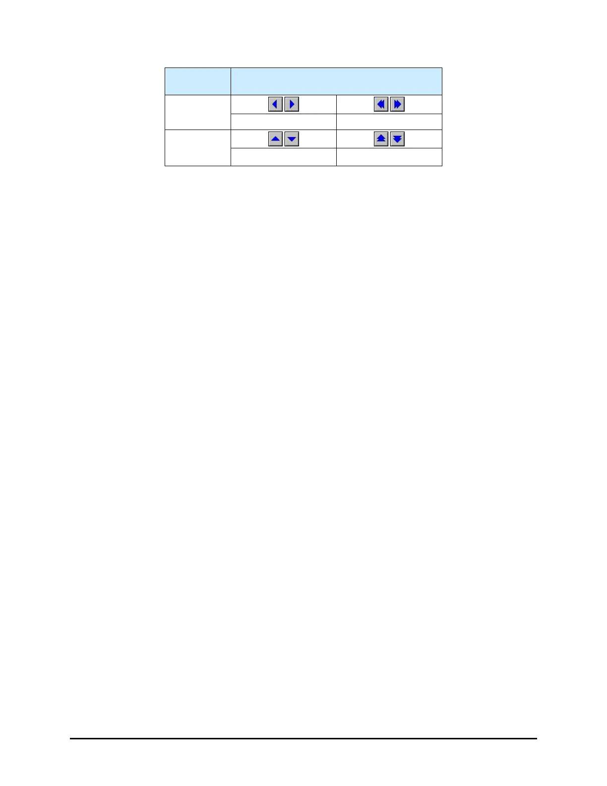
Table 4-2 Conveyor Jog Controls: Jog Distance
(1)
Movement
Distance
(2)
X
0.0254 (0.001) 1.27 (0.0500)
Y
0.0254 (0.001) 1.27 (0.0500)
Notes: (1) Default distances. Refer to the Fluidmove User Guide or
Fluidmove Online Help to modify jog distances.
(2) Distance per mouse click on the arrow button.
4.7.2.1 Dual Conveyor Systems
If the dispensing system is equipped with dual conveyors, the Conveyor 2 radio button will be active.
Click on the Conveyor 1 radio button to activate the Conveyor 1 jog controls, click on the Conveyor 2
radio button to activate the Conveyor 2 jog controls.
1. Conveyor 1 jog controls operate as follows:
On the X-Y control panel, the arrows pointing to the Left move the Conveyor 1 belt to
the left and the arrows pointing to the Right move it to the right.
On the X-Y control panel, the arrows pointing Up move the Conveyor 1 rear rail toward
the back of the dispensing area and the arrows pointing Down move the rear rail toward
the front of the dispensing area.
2. Conveyor 2 jog controls operate as follows:
On the X-Y control panel, the arrows pointing to the Left move the Conveyor 2 belt to
the left and the arrows pointing to the Right move it to the right.
On the X-Y control panel, the arrows pointing Up move the Conveyor 2 rear rail toward
the back of the dispensing area and the arrows pointing Down move the rear rail toward
the front of the dispensing area.
NOTES The selected jog device is indicated in the bottom right-hand corner of all major
Fluidmove windows.
Refer to Table 4-3 for a detailed explanation of jog control commands for both the
dispensing head and conveyor.

 Loading...


