Calibration and Adjustment 5-19
4. Connect the external pressure gauge to the desired connection
(valve, fluid, or cooling) on the dispensing system bulkhead
(Figure 5-20) using a quick disconnect fitting.
For the valve pressure reading, insert the external pressure
gauge hose into the black Valve 1 Off connection on the
bulkhead. If there is no reading, connect the hose to the
blue Valve 1 ON connection.
You should now have a reading at the digital gauge.
5. Compare the external gauge pressure reading to the set point
displayed on the Air Pressure tab (Figure 5-19).
Figure 5-20 Dispensing
System Bulkhead
6. If the pressure reading on the external pressure gauge does not match the software set
point, click on the value in the "Set Point Offset" column and enter the difference between
the actual output (reading on the external gauge) and the set point on the Air Pressure tab.
Click on
Apply. A positive value will increase the output, and negative value will lower
the output. For example, if the gauge reading is 80.2 and the software set point is 80.0,
enter -0.2 in the “Set Point Offset” column. The external gauge output should now be 80.0.
After the set point has been calibrated, it is necessary to calibrate the external pressure
gauge to the software reading.
To calibrate the Fluidmove Current Pressure Reading to the External Gauge Reading:
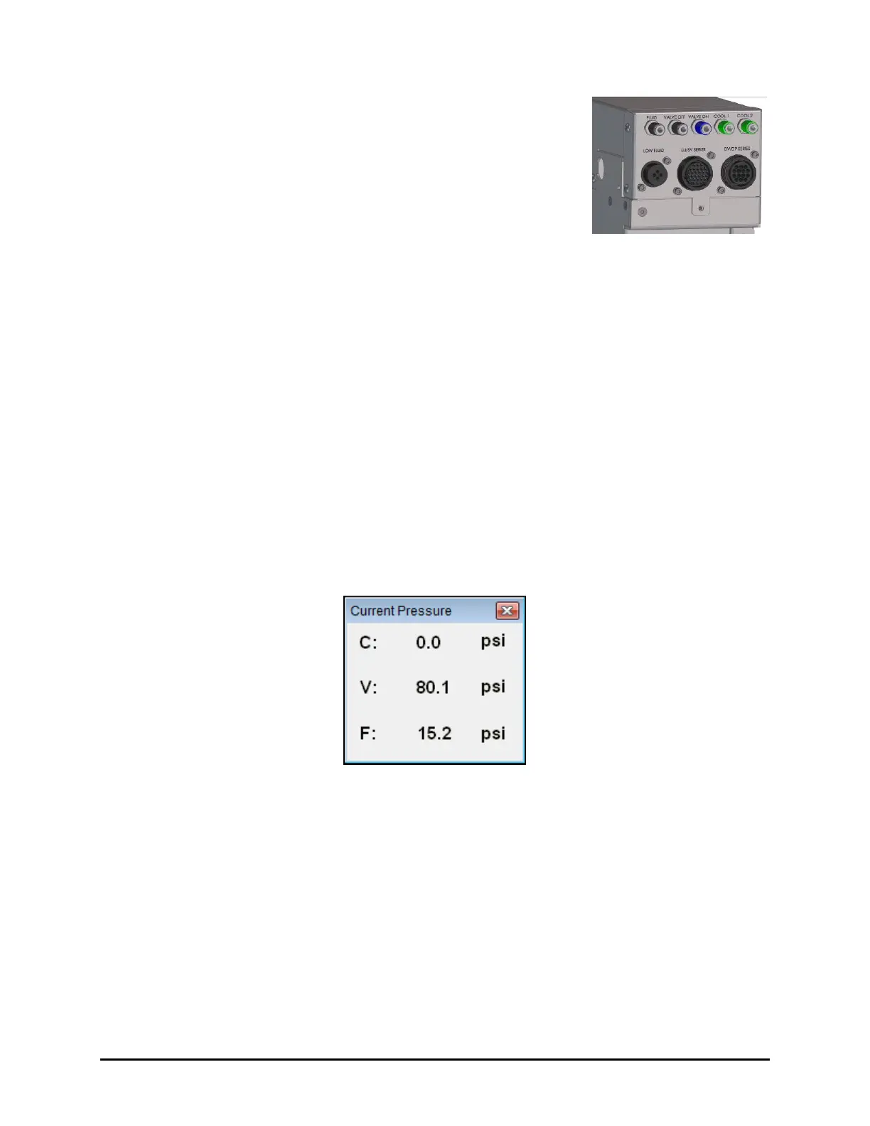
1. Press [Ctrl + P] on the dispensing system keyboard to open the Current Pressure window
(Figure 5-21).
The current pressure is the same as the pressure shown in the “Reading” column on the
Air Pressure tab in the Local Machine Offsets window (Figure 5-19).
Figure 5-21 Current Pressure Window
2. If the reading on the external gauge does not match the current pressure reading in the
software, click on the value in the “Reading Offset” column (Figure 5-19) and enter the
difference between the actual output (reading on the digital gauge) and the reading on the
Air Pressure tab. Click on
Apply.
A positive value will increase the reading, and negative value will lower the reading.
For example, if the gauge reading is 80.0 and the software reading is 75.0, enter 5.0 in
the Reading Offset column. The software reading will change to 80.0.
3. When all applicable outputs have been calibrated, click
OK in the Local Machine Offsets
Window. The values are now set and the E/P controllers are calibrated.

 Loading...


