5-32 Calibration and Adjustment
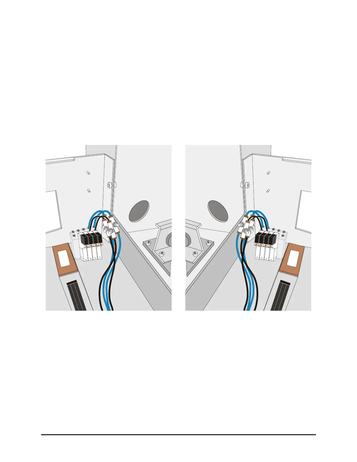
5. Locate the Flow Control Valves (FCVs) for the appropriate lift table.
NOTE Flow Control Valve locations are shown in Figure 5-36 to Figure 5-38. If the
system has dispense heat only, the FCVs are located under the lift table. To
gain access to the FCVs, it may be necessary to move the dispensing head to
the rear of the machine.
6. Adjust the FCV with the black hose for upward speed and the FCV with the blue hose for
downward speed.
7. Close the hatch and toggle the lift output buttons to test the speed (Figure 5-35).
8. Repeat Step 6 and Step 7 until you are satisfied with the lift table operation.
9. When done, exit conveyor setup and return to the Fluidmove Main Window.
Figure 5-36 Pre-Dispense Lift Table Controls
Figure 5-37 Post-Dispense Lift Table Controls

 Loading...


