6-20 Maintenance
6. With the X-axis linear encoder and mounting bracket removed, lay the mounting bracket on
a flat surface with the sensor window facing down.
7. Loosen the two (2) read head mounting screws securing the linear encoder head in the
bracket (Figure 6-14).
8. Lower the linear encoder head and rest the linear encoder head against the flat surface.
9. Tighten the two (2) read head mounting screws to secure the head in that position (flush
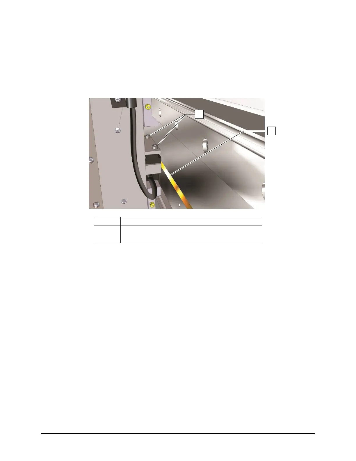
against the flat surface) (Figure 6-14).
-
Read Head Mounting Screws
Figure 6-14 X-Axis Encoder Read Head Mounting Screws
10. Reinstall the linear encoder and mounting bracket.
11. Tighten the two (2) read head mounting screws to secure the encoder in place.
12. Reinstall the two (2) Z-head panel screws and camera bracket screws.
13. Manually move the dispensing head left and right and make sure that the encoder LED
remains green when in motion.
If the LED turns red or orange when the axis is in motion, repeat Step 6 through Step 12
and adjust the encoder height again.
If the LED turns red or orange in a specific location, it may be due to an obstruction or
a damaged encoder strip. Use a soft cloth and mild cleanser to clean that location. If the
problem is not resolved, repeat Step 6 through Step 12 and adjust the encoder height
again.
14. When the LED stays green throughout the entire dispensing head travel, close the
dispensing system hatch and restart Fluidmove.
15. Observe the dispensing head motion to ensure the dispensing head initializes and finds
home correctly.

 Loading...


