18 Monitoring EEG
281
Changing the Impedance Limit
The impedance limit can be set for all electrodes simultaneously in the Setup EEG menu, or in the EEG
Impedance / Montage
window using the pop-up keys. If the limit is exceeded during monitoring, an
INOP will appear and the graphic impedance indicator will change.
To change the impedance limit, either
• use the pop-up keys that appear with the
EEG Impedance / Montage window, or
•in the
Setup EEG menu, select Impedance Limit to call up a list of selections between 0 and
30 kOhm, then select the required limit from this list.
About Electrode-to-Skin Impedance
Electrode-to-skin impedance is the main quality indicator for the measured EEG signal. During
normal EEG monitoring, electrode-to-skin impedance is measured continuously and disconnected
electrodes are detected. The impedance value for each single, independent signal electrode is displayed
in the
EEG Impedance / Montage window. If the measured electrode-to skin impedance of one or
more electrodes is above the limit, an INOP will be issued.
For impedance measurement at least two electrodes, plus the reference electrode, must be connected.
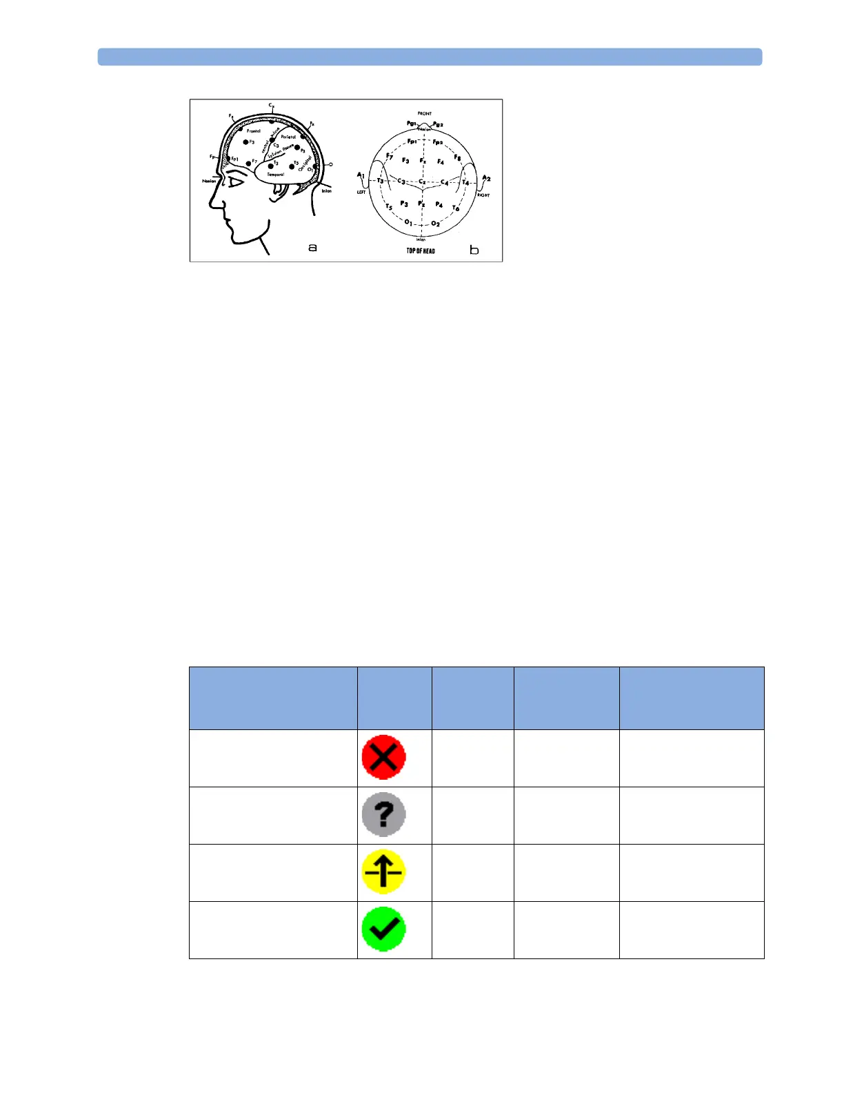
Impedance Indicators
Electrode/Skin
Impedance
Symbol Color Displayed
Impedance
Value
Action
Electrode not connected red no value connect electrode
Noisy signal gray 60 kΩ (fixed) check electrode-to-skin
connections
Electrode connected,
impedance above limit
yellow measured value
(e.g. 15 kΩ)
check limit, check
electrode-to-skin
contact
Electrode connected,
impedance at or below limit
green measured value
(e.g. 3 kΩ)
no action necessary