Section 22: HEATING AND AIR CONDITIONING
PA1553
24
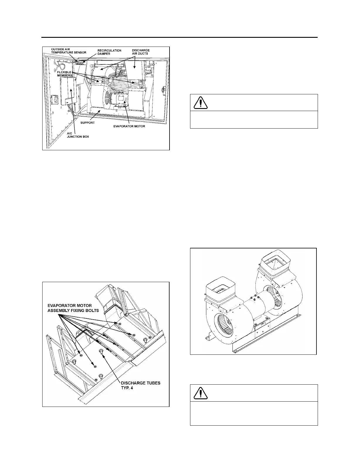
FIGURE 22: EVAPORATOR COMPARTMENT 22314
9.3.1 Removal
1. Set the ignition key switch to the “OFF”
position and trip circuit breakers CB1 &
CB2.
2. Open the last L.H. side baggage
compartment door. Pull the black release
button located on the L.H. side in order to
unlock and open the evaporator
compartment door.
3. Remove the evaporator motor and coil
access panel.
4. Identify the L.H. side discharge duct inside
compartment and remove the Phillips head
screws retaining the flexible member to
duct.
FIGURE 23: EVAPORATOR MOTOR ASSY FIXING BOLTS
5. Repeat step 4 for the R.H. side air duct.
6. Disconnect the electrical motor speed
control connections on the motor plate.
7. From under the vehicle, remove the eight
bolts retaining the evaporator fan motor
support. Remove the complete unit from the
evaporator compartment (Fig. 23 & 24).
CAUTION
Never support evaporator motor by its output
shafts while moving it.
8. On a work bench, unscrew the fan square
head set screws, the Phillips head screws
retaining cages to support and slide out the
assemblies from the evaporator motor
output shaft.
9.3.2 Installation
To reinstall the evaporator motor, reverse
"Evaporator Motor Removal" procedure.
9.3.3 Checking Operation of Brush in Holder
Lift brush slightly 1/8 inch (3 mm) and release it.
The spring should push the brush freely back
into the holder securing it against the
commutator.
FIGURE 24: EVAPORATOR MOTOR ASSEMBLY 22316
9.3.4 Brush Wear Inspection and
Replacement
CAUTION
Only use replacement brushes recommended
by the manufacturer. Not doing so will void
warranty.
 Loading...


