SERIES 60 SERVICE MANUAL
The Jake Brake is electronically controlled. Jake Brake control system wiring will vary depending
on the vehicle manufacturer. For a general overview of the Jake Brake, see Figure 1-416 and
see Figure 1-416a.
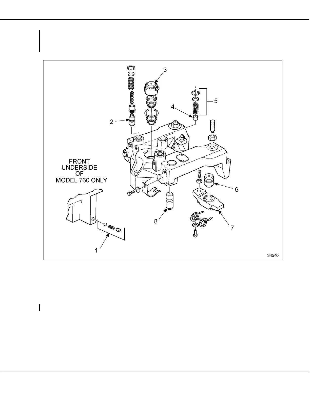
1. Ball Check Valve (Model 760 Only) 5. Power Lash Assembly
2. Control Valve 6. Slave Piston
3. Solenoid Valve 7. Bridge
4. Accumulator Piston 8. Master Piston
Figure 1-416 Typical Model 760, 765, or 770 Jake Brake Assembly
All information subject to change without notice.
6SE483 9901 Copyright © 1999 DETROIT DIESEL CORPORATION From Bulletin 16-60-99 1-527
 Loading...


