112 Rockwell Automation Publication 2198-UM002L-EN-P - October 2021
Chapter 4 Connector Data and Feature Descriptions
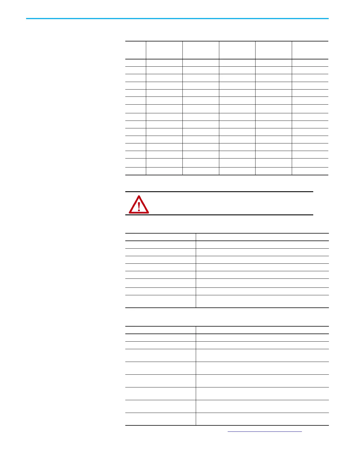
Table 53 - Universal Feedback Signals by Device Type
UFB Pin Hiperface
Generic TTL
Incremental
Generic Sine/
Cosine
Incremental
EnDat Sine/
Cosine
EnDat Digital
1 MTR_SIN+ MTR_AM+ MTR_SIN+ ENDAT_B+ –
2 MTR_SIN– MTR_AM– MTR_SIN– ENDAT_B– –
3 MTR_COS+ MTR_BM+ MTR_COS+ ENDAT_A+ –
4 MTR_COS– MTR_BM– MTR_COS– ENDAT_A– –
5 MTR_DATA+ MTR_IM+ MTR_IM+ MTR_DATA+ MTR_DATA+
6 MTR_ECOM MTR_ECOM MTR_ECOM MTR_ECOM MTR_ECOM
7
MTR_EPWR9V
(1)
(1) Determine which power supply your encoder requires and connect to only the specified supply. Do not make connections to
both supplies.
––
MTR_EPWR9V
(1)
MTR_EPWR9V
(1)
8 – MTR_S3 MTR_S3 – –
9 – – – MTR_CLK+ MTR_CLK+
10 MTR_DATA– MTR_IM– MTR_IM– MTR_DATA– MTR_DATA–
11 MTR_TS MTR_TS MTR_TS MTR_TS MTR_TS
12 – MTR_S1 MTR_S1 – –
13 – MTR_S2 MTR_S2 – –
14
MTR_EPWR5V
(1)
MTR_EPWR5V MTR_EPWR5V
MTR_EPWR5V
(1)
MTR_EPWR5V
(1)
15–––MTR_CLK–MTR_CLK–
ATTENTION: To avoid damage to components, determine which
power supply your encoder requires and connect to either the 5V or
9V supply, but not both.
Table 54 - Hiperface Specifications
Attribute Value
Memory support Not programmed, or programmed with Allen-Bradley motor data
Hiperface data communication 9600 baud, 8 data bits, no parity
Sine/cosine interpolation 4096 counts/sine period
Input frequency (AM/BM) 250 kHz, max
Input voltage (AM/BM) 0.6...1.2V, peak to peak, measured at the drive inputs
Line loss detection (AM/BM)
Average (sin
2
+ cos
2
) > constant
Noise filtering (AM and BM) Two-stage coarse count pulse reject filter with rejected pulse tally
Incremental position verification
Position compare between incremental accumulator and serial data
performed every 50 ms or less
Table 55 - Generic TTL Incremental Specifications
Attribute Value
TTL incremental encoder support 5V, differential A quad B
Quadrature interpolation 4 counts / square wave period
Differential input voltage
(MTR_AM, MTR_BM, and MTR_IM)
5V DC, differential line driver (DLD) output compatible
DC current draw
(MTR_AM, MTR_BM, and MTR_IM)
30 mA, max
Input signal frequency
(MTR_AM, MTR_BM, and MTR_IM)
5.0 MHz, max
Edge separation
(MTR_AM and MTR_BM)
42 ns min, between any two edges
Commutation verification
(1)
(1) These could be with or without HALL effects (UVW). Refer to Commutation Self-sensing Startup on page 436.
Commutation angle verification performed at the first Hall signal
transition and periodically verifies thereafter
Hall inputs
(MTR_S1, MTR_S2, and MTR_S3)
Single-ended, TTL, open collector, or none

 Loading...


