122 Rockwell Automation Publication 2198-UM002L-EN-P - October 2021
Chapter 5 Connect the Kinetix 5700 Drive System
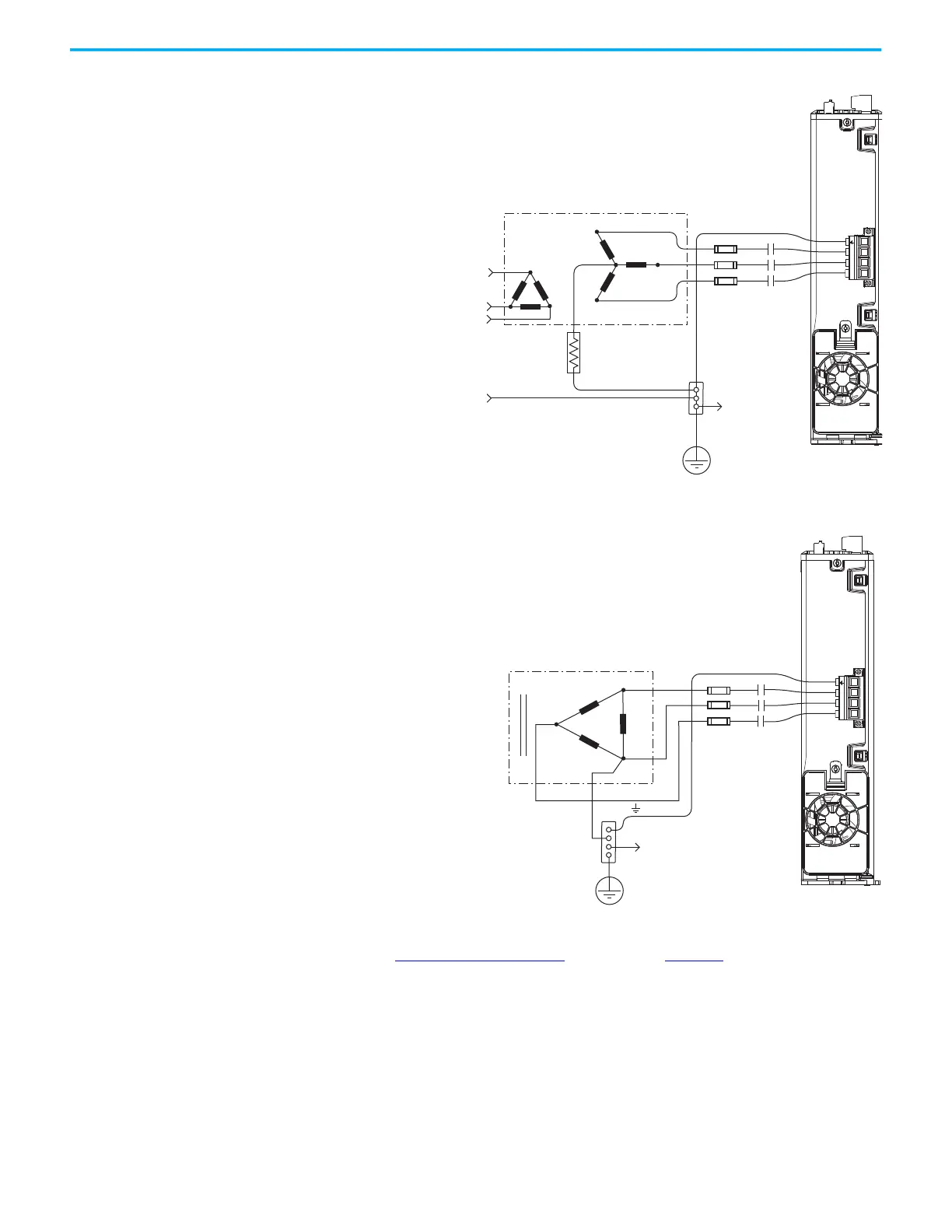
Figure 73 - Impedance-grounded Power Configuration (WYE secondary)
(1) 2198-Pxxx power supply has the ground jumper removed. 2198-xxxx-ERSx inverters have the ground jumpers removed.
Figure 74 - Corner-grounded Power Configuration (Delta secondary)
(1) 2198-Pxxx power supply has the ground jumper removed. 2198-xxxx-ERSx inverters have the ground jumpers removed.
Refer to Power Wiring Examples beginning on page 321 for input power
interconnect diagrams.
Transformer
Three-phase
Input VAC
Phase Ground
Transformer (WYE) Secondary
Ground Grid or
Power Distribution Ground
Connect to
drive module
ground stud.
Circuit
Protection
M1
Contactor
Bonded Cabinet
Ground
2198-Pxxx DC-bus Power Supply
(1)
(bottom view)
L3
L1
L2
L3 L2 L1
Transformer (Delta) Secondary
Bonded Cabinet
Ground
Transformer
Ground Grid or
Power Distribution Ground
Connect to drive module
ground stud.
Circuit
Protection
M1
Contactor
2198-Pxxx DC-bus Power Supply
(1)
(bottom view)

 Loading...


