Rockwell Automation Publication 2198-UM002L-EN-P - October 2021 123
Chapter 5 Connect the Kinetix 5700 Drive System
Ungrounded Power Configurations
The ungrounded power configuration (Figure 75), corner-grounded
(Figure 74
), and impedance-grounded (Figure 73) power configurations do not
provide a neutral ground point.
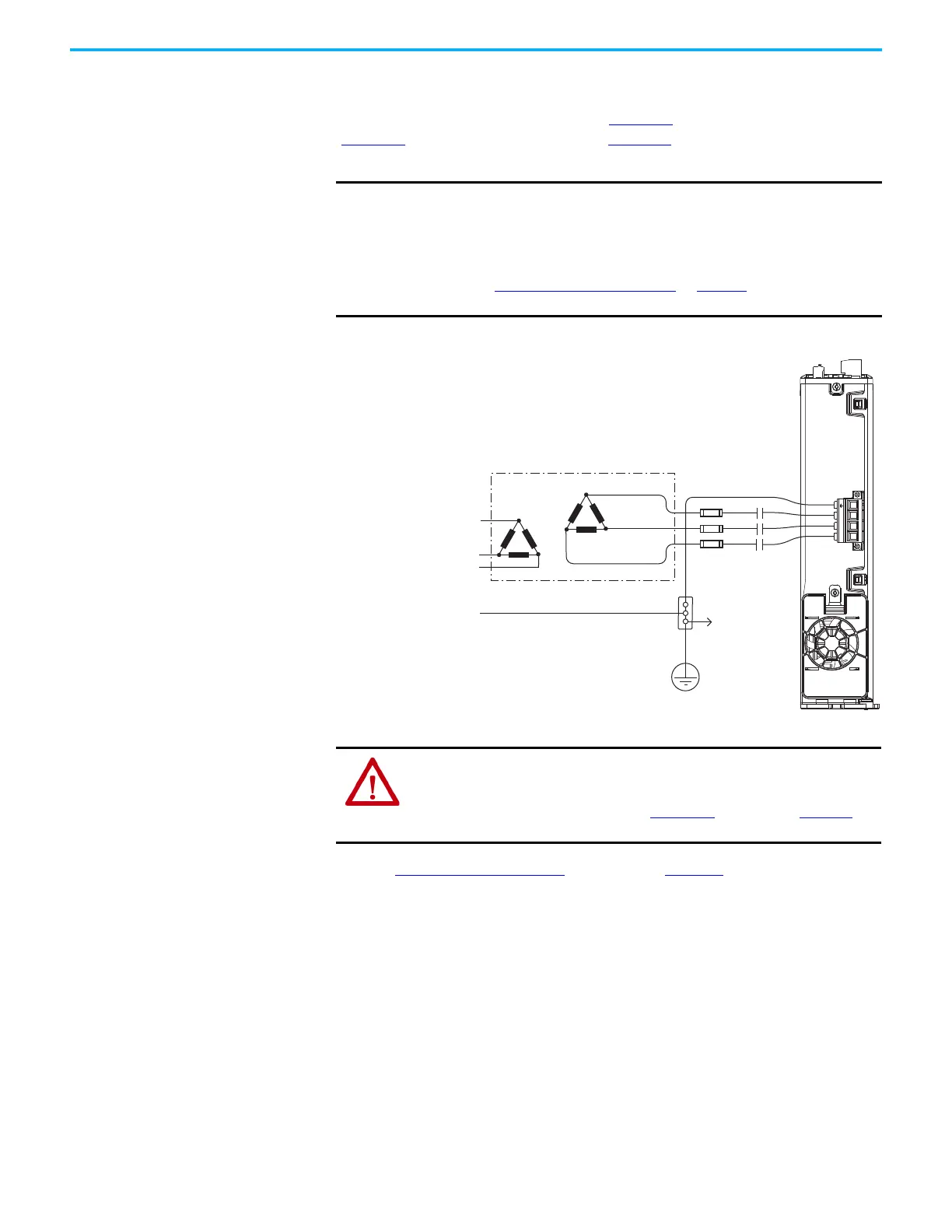
Figure 75 - Ungrounded Power Configuration
(1) 2198-Pxxx power supply has the ground jumper removed. 2198-xxxx-ERSx inverters have the ground jumpers removed.
Refer to Power Wiring Examples beginning on page 321 for input power
interconnect diagrams.
IMPORTANT
If you determine that you have ungrounded, corner-grounded, or
impedance-grounded power distribution in your facility, you must
remove the ground screw in each of your DC-bus power supplies, iTRAK
power supplies, and dual-axis inverters, and the ground jumper in each
of your single-axis inverters.
Refer to Ground Screw/Jumper Settings
on page 127 for more
information.
Transformer
Three-phase
Input VAC
Chassis Ground
Bonded Cabinet
Ground
Ground Grid or
Power Distribution Ground
Connect to
drive module
ground stud.
Circuit
Protection
M1
Contactor
2198-Pxxx DC-bus Power Supply
(1)
(bottom view)
ATTENTION: Ungrounded and corner-grounded systems do not reference
each phase potential to a power distribution ground. This can result in an
unknown potential to earth ground. Drive-to-motor cable lengths are limited
with these AC power source types. See Appendix D
, beginning on page 383,
for more information.

 Loading...


