Rockwell Automation Publication 2198-UM002L-EN-P - October 2021 125
Chapter 5 Connect the Kinetix 5700 Drive System
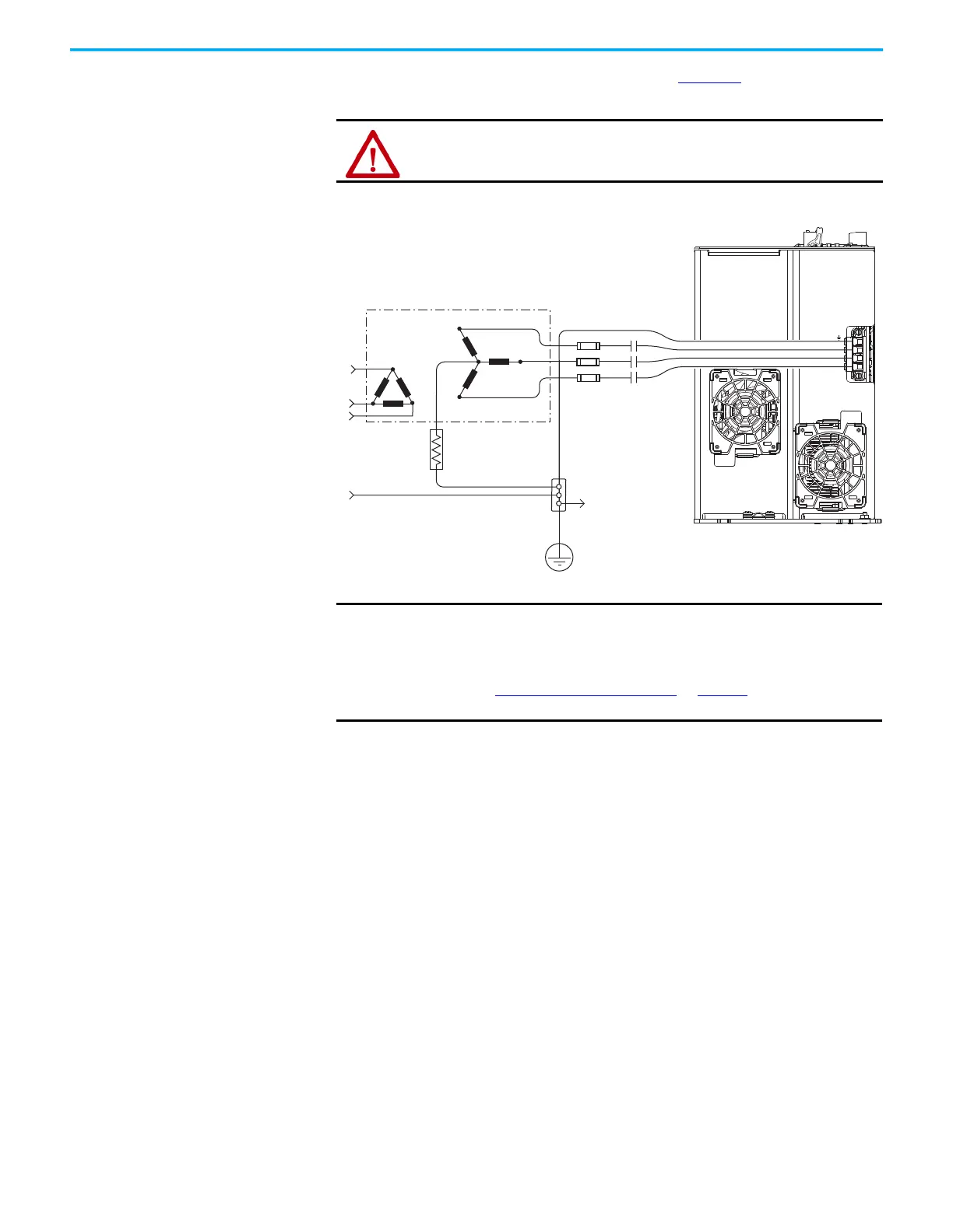
This impedance-grounded power configuration (Figure 77) does not provide a
neutral ground point.
Figure 77 - Impedance-grounded Power Configuration (WYE secondary)
(1) 2198-RPxxx power supply has the ground jumper removed. 2198-xxxx-ERSx inverters have the ground jumpers removed.
ATTENTION: Ungrounded systems do not reference each phase potential to
a power distribution ground. This can result in an unknown potential to
earth ground.
L3
L2
L1
L3
L2
L1
Transformer
Three-phase
Input VAC
Phase Ground
Transformer (WYE) Secondary
Ground Grid or
Power Distribution Ground
Connect to drive
module ground stud.
Circuit
Protection
2198-RPxxx
(1)
Regenerative Bus Supply
(bottom view)
M1
Contactor
Bonded Cabinet
Ground
IMPORTANT
If you determine that you have impedance-grounded power distribution
in your facility, you must remove the ground screw in your regenerative
power supply, iTRAK power supplies, and dual-axis inverters, and the
ground jumper in each of your single-axis inverters.
Refer to Ground Screw/Jumper Settings
on page 127 for more
information.

 Loading...


