Rockwell Automation Publication 2198-UM002L-EN-P - October 2021 165
Chapter 5 Connect the Kinetix 5700 Drive System
Motor Feedback Cable Preparation
Observe the lead preparation guidelines for each of the connector kits.
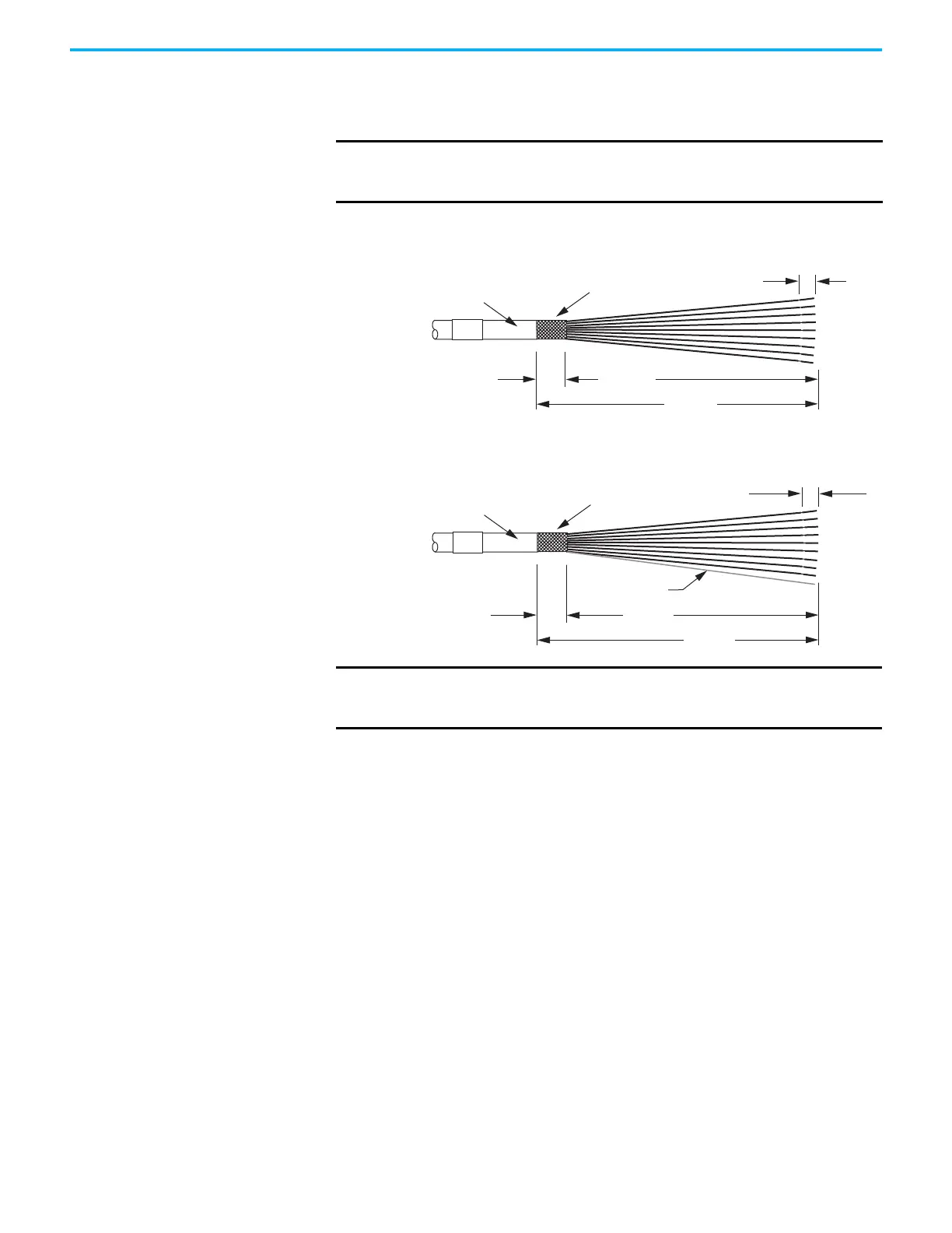
Figure 108 - Lead Preparation for 2198-H2DCK Converter Kit
Figure 109 - Lead Preparation for 2198-K57CK-D15M Connector Kit
IMPORTANT
This length of wire is needed to provide a service loop for the longest
wires terminated at the terminal block. However, most wires need to be
trimmed shorter, depending on the terminal they are assigned to.
12.0 (0.5)
5.0 (0.2)
115 (4.5)
103 (4.0)
Cable Jacket
Cable Shield
Dimensions are in mm (in.)
12.0 (0.5)
5.0 (0.2)
110 (4.3)
97 (3.8)
Drain Wire
Cable Jacket
Cable Shield
Dimensions are in mm (in.)
Drain Wire
IMPORTANT
For the 2198- K57CK-D15M universal connector kit, if your Kinetix 2090
motor cable does not include a drain wire, you must create one from the
overall shield during wire preparation and connect it to pin 16.

 Loading...


