164 Rockwell Automation Publication 2198-UM002L-EN-P - October 2021
Chapter 5 Connect the Kinetix 5700 Drive System
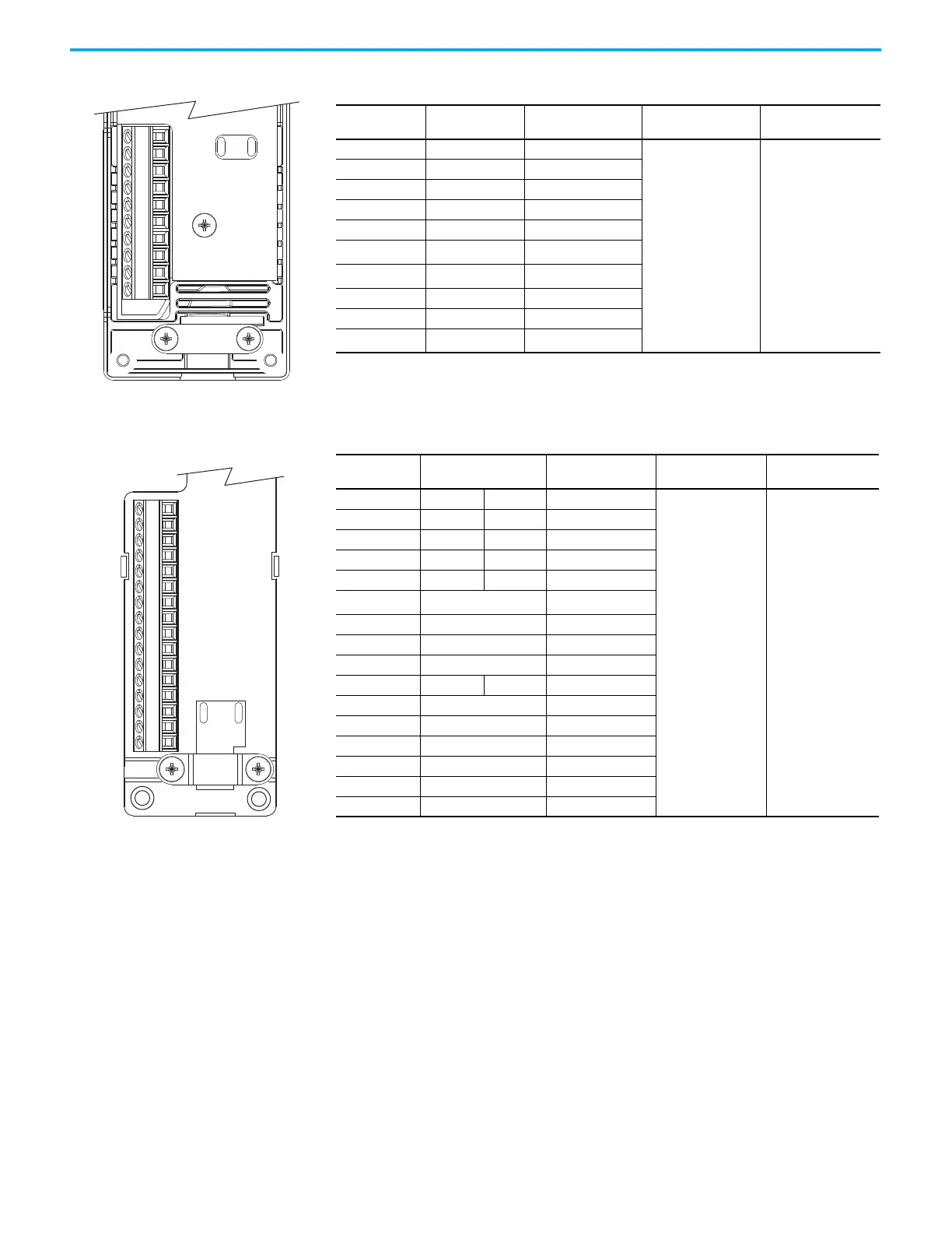
Figure 106 - 2198-H2DCK Converter Kit Pinout
Figure 107 - 2198-K57CK-D15M Connector Kit Pinout
Terminal Signal Wire Color
Strip Length
mm (in.)
Torque Value
N•m (lb•in)
1 SIN+ Black
5.0 (0.2)
0.22…0.25
(1.9…2.2)
2 SIN– White/Black
3 COS+ Red
4 COS– White/Red
5 DATA+ Green
6
ECOM
(1)
(1) The ECOM and TS- connections are tied together and connect to the cable shield.
White/Gray
7
EPWR_9V
(2)
(2) The converter kit generates 9V and 5V from a 12V supply coming from the drive. The 9V supply is used by 9V encoders in
460V motors and actuators.
Orange
10 DATA– White/Green
11 TS White/Orange
14
EPWR_5V
(2)
Gray
10-pin
Connector
1
2
34
5
678
910111213141516
16-pin
Connector
Terminal Signal Wire Color
Strip Length
mm (in.)
Torque Value
N•m (lb•in)
1 SIN+ AM+ Black
5.0 (0.2)
0.22…0.25
(1.9…2.2)
2 SIN– AM– White/Black
3 COS+ BM+ Red
4 COS– BM– White/Red
5 DATA+ IM+ Green
6
ECOM
(1)
(1) The ECOM and TS- connections are tied together and connect to the cable shield.
White/Gray
7 EPWR_9V Orange
8 S3 White/Yellow
9CLK+ Brown
10 DATA– IM– White/Green
11 TS White/Orange
12 S1 White/Blue
13 S2 Yellow
14 EPWR_5V Gray
15 CLK– White/Brown
16 Drain N/A

 Loading...


