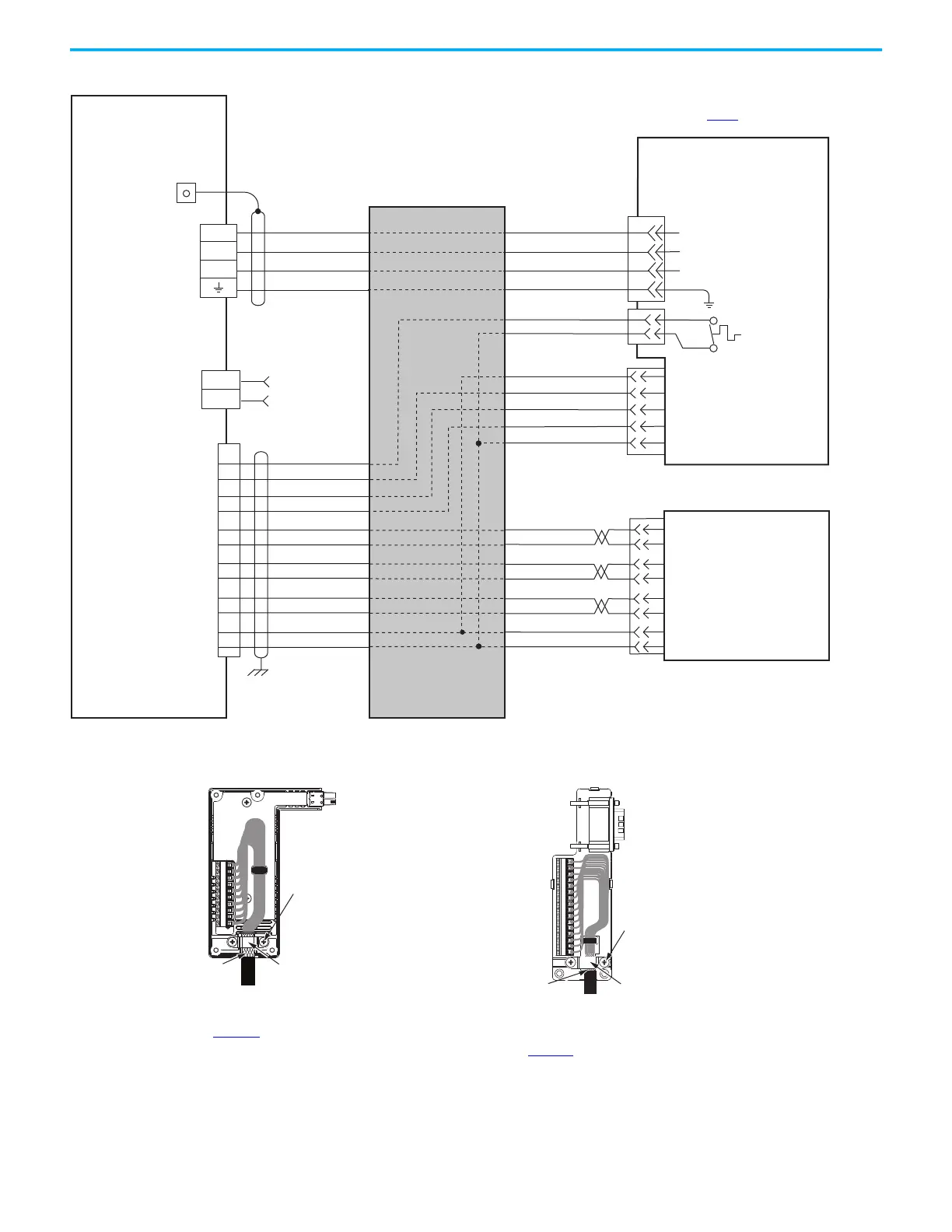
LDC-Cxxxxxx-xHTx0
Linear Motor Coil with
Sin/Cos or TTL External Encoder
and Flying-lead Cables
Three-phase
Motor Power
Motor Feedback
(MF) Connector
Thermostat
Refer to table on page 319 for note information.
External
Sin/Cos or (TTL)
Encoder
Hall Effect
Module
Wire as shown using
cable type appropriate for
your application.
Motor Power
(MP) Connector
Cable Shield
Clamp
Note 7
2198-Dxxx -ERSx
Kinetix 5700 Servo Drives
Universal Feedback
(UFB) Connector
Note 8
Grounding Techniques for Feedback Cable Shield
Cable Clamp
Exposed shield secured
under clamp.
Clamp Screws (2)
2198-H2DCK
Hiperface-to-DSL
Feedback Converter Kit
Cable Clamp
Exposed shield secured
under clamp.
Clamp Screws (2)
Refer to Universal Feedback Connector
Kit Installation Instructions, publication
2198-IN010
, for connector kit
specifications.
2198-K57CK-D15M
Universal Feedback
Connector Kit
Refer to Hiperface to DSL Feedback
Converter Kit Installation Instructions,
publication 2198-IN006
, for converter kit
specifications.

 Loading...


