EasyManua.ls Logo

Rockwell Automation Allen-Bradley Kinetix 5700 - Page 357

Rockwell Automation Allen-Bradley Kinetix 5700
456 pages
To Next Page IconTo Next Page
To Previous Page IconTo Previous Page
Loading...
Rockwell Automation Publication 2198-UM002L-EN-P - October 2021 357
Appendix A Interconnect Diagrams
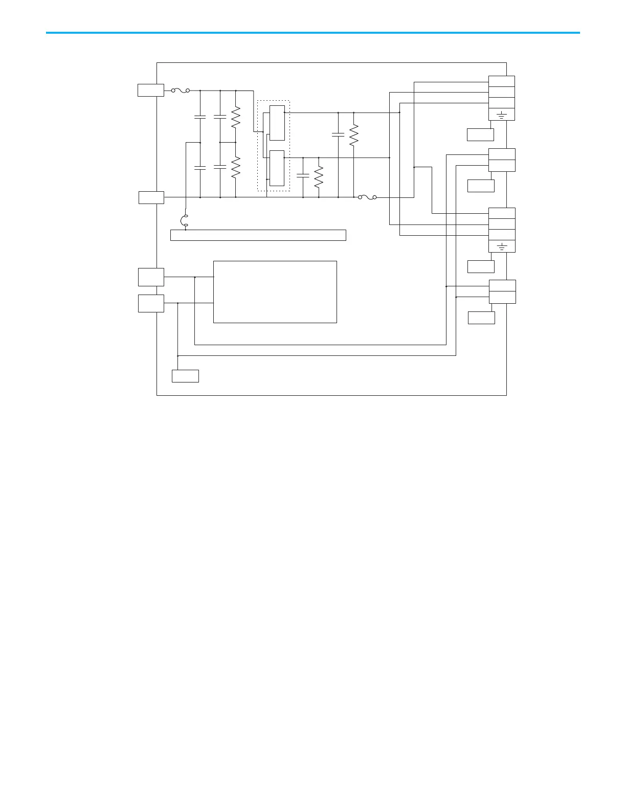
Figure 197 - iTRAK Power Supply Block Diagram
(1) Ground screw in the installed (default) configuration.
(2) Connection from 24V- to Chassis is made inside of the iTRAK power supply.
24V+
24V–
DC+
DC–
DC-
L
H
24V+
24V–
DC-
L
H
24V+
24V–
H
L
DC-
Ground Jumper
(1)
Control
Chassis
Chassis
Chassis
Chassis
Chassis
2x DC-DC
Converters
DC-bus Output
IDC Connector - A
24V Control Output
ICP Connector - A
DC-bus Output
IDC Connector - B
24V Control Output
ICP Connector - B
Ground Connection
(2)
Chassis
24V Control Power
(CP) Connector
DC-bus Power
(DC) Connector

Table of Contents

Other manuals for Rockwell Automation Allen-Bradley Kinetix 5700

Related product manuals