Section07ELECTRICALSYSTEM
Subsection 04 (INSTRUMENTS AND ACCESSORIES)
smr2005-060-004_a
Select the exterior temperature mode in the Infor-
mation Center.
Useaheatgunandwarmupthesensor. Thetem-
perature should raise rapidly on the gauge.
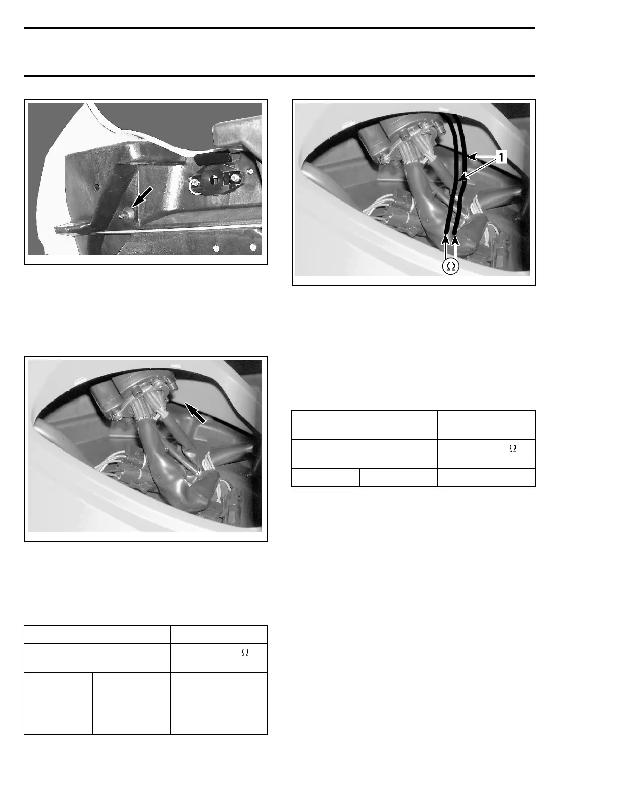
Otherwise, open top storage compartment cover
to reach sensor.
smr2005-060-005_a
Unplug connector from temperature sensor.
Connect a temporary 2-pin connector with wires
to sensor.
Measure sensor resistance to end of temporary
wires.
SENSOR TEST WIRES MEASUREMENT
PIN
RESISTANCE @
20°C(68°F)
A B
Resistance
according to
the ambient
temperature.
See table below.
smr2005-060-005_b
1. Sensor test wires
Remove test wires.
If resistance is out of specification, replace sensor.
Otherwise, perform the following procedure.
Exterior Temperature Input
Unplug connector from temperature sensor.
Connect potentiometer test probes as follows.
MAIN HARNESS
CONNECTOR
MEASUREMENT
PIN
RESISTANCE @
20°C(68°F)
B C See table below.
Adjust potentiometer to the resistance values as
per following chart to test the accuracy of the In-
formation Center.
204 smr2005-060