DMG 3200/3100/3000 – User Manual
Page 138 (306)
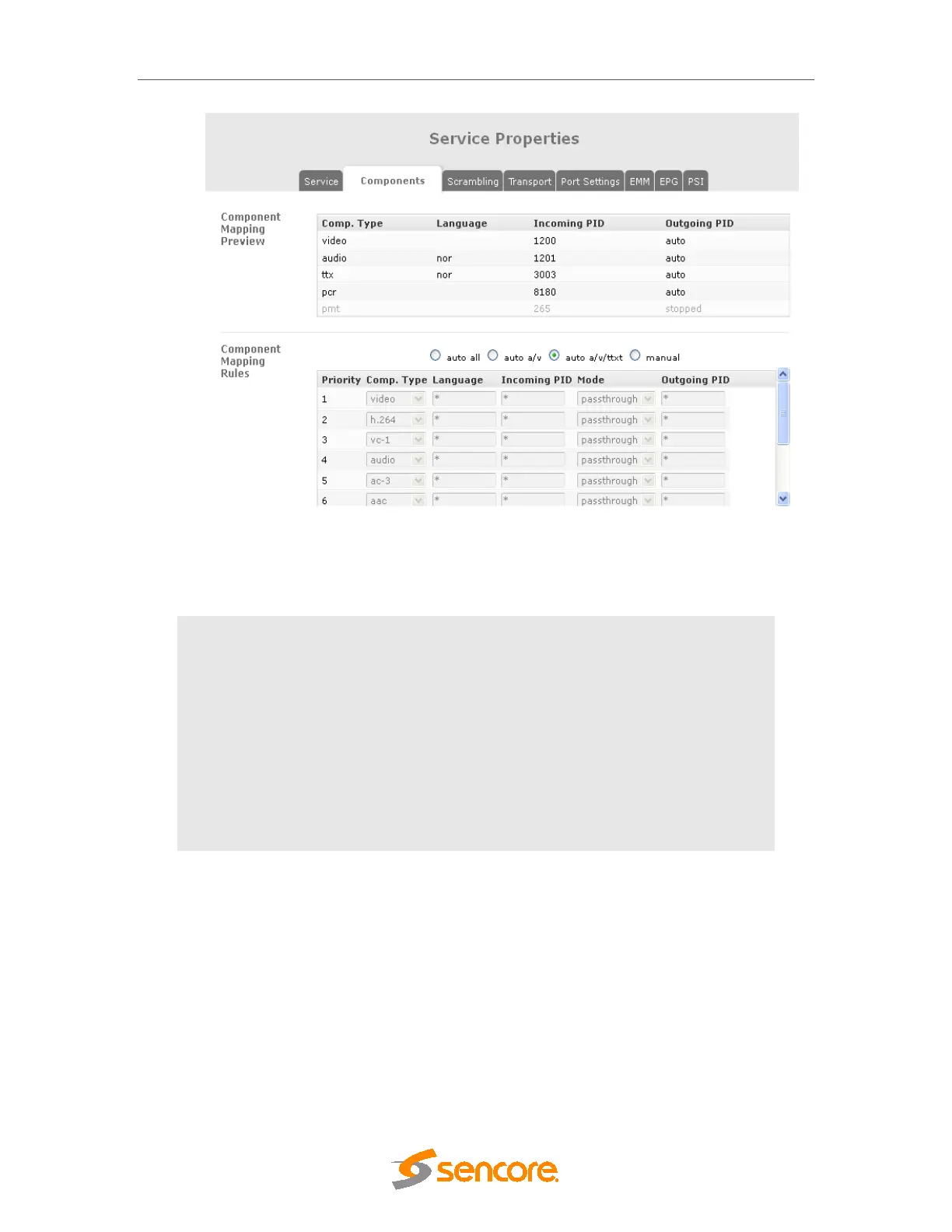
Figure 7.24 - Components Tab for IP SPTS
The following mapping modes are available:
Auto All
All PIDs will be mapped to the output
Auto A/V
Only Audio and Video PIDs will be mapped. If multiple Audio
PIDs are available on the inputs, all will be mapped through.
Auto A/V/TTXT
Audio, Video, Teletext and DVB Sub PIDs will be mapped. If
multiple Audio PIDs are available on the inputs, all will be
mapped through.
Manual
It is possible to define your own custom filtering and mapping
rules to get the desired output. Refer to the detailed description
below.
7.3.8.1 Manual Mapping
In Manual mode it is up to the user to define the mapping rules for the components of the
outgoing service. Each outgoing PID requires a dedicated rule; otherwise the default rule
applies.
A component-type PID mapping mode can be set, i.e. the input component type is used to
identify the input PID itself, instead of using the input PID value only. This feature is typically
used to provide a fixed PID line-up at the output, even if the input PID values are changing
dynamically at the input.
To achieve component-type PID mapping, a set of mapping rules are applied to the incoming
PID which matches a specific filter. Several rules/filters can be added, and one PID may match