DMG 3200/3100/3000 – User Manual
Page 28 (306)
3.4 Connecting Output Signals
3.4.1 IP Output
This applies to the following modules:
• Standalone IP Output
• Dual IP module (Output mode)
The standalone IP output card is equipped with both an electrical connector (RJ45) and one
optical (via the SFP module) for data. The RJ45 connector marked “control” is not in use. It is
not required to configure the IP address or connect the port to the IP network.
The Dual IP module is equipped with two electrical connectors (RJ45) and two SFP connector.
Automatic sensing of 10/100/1000Mbit Ethernet connections is supported. For a 1000Mbit
connection, the Ethernet cable must be a category 6 cable.
The IP address for both the electrical (RJ45) and the optical (SFP) connectors for data is the
same. Consequently, both connectors cannot be used simultaneously. These inputs are
automatically activated by IP connection. The first port activated (by establishing a link to the
router) will be the active port. To activate the other port, remove the cable from the active port.
3.4.2 ASI Output
Each ASI output module has four independent ASI outputs. The ASI connector is a 75Ω BNC
connector. The maximum output rate per connector is 212Mbit/s in burst mode.
3.4.3 QAM Output
Each QAM output module has two 75Ω F connectors which carry up to sixteen frequencies.
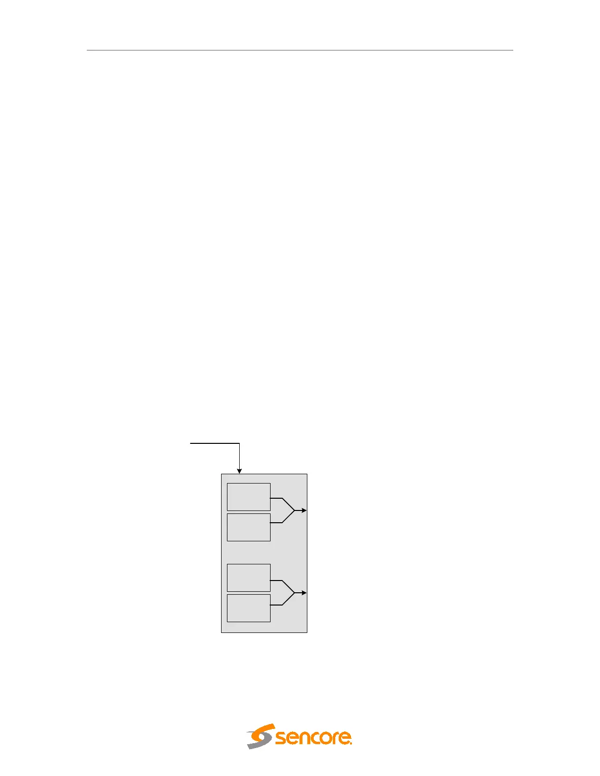
Data from backplane
MOD 1
MOD 2
MOD 3
MOD 4
QAM Modulator board
The QAM modulator consists of
four modulator chips, each
carrying up to
4 carriers. The
frequency is set only for the first
carrier of each modulator. The
remaining three carriers per
modulator follow regular spacing.
Figure 3.2 - QAM Modulator