DMG 3200/3100/3000 – User Manual
Page 22 (306)
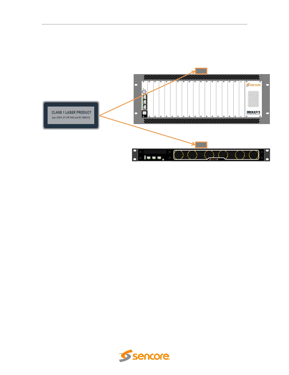
2.1.6.3 Labels
The following illustrations show the labels attached to the Sencore products, according to
the standards.
A classification label is attached to the top cover of the DMG 3000/3100/3200 products.
Figure 2.12 - classification label
3 Physical Module Configuration
3.1 Connecting switch modules
Configuration, management and monitoring of your Sencore unit is done via the management
port on the switch module. The switch module will contain the database for the full configuration
of the unit. One switch module (in some configuration two switch modules) must be installed in
all 1 RU and all 4 RU chassis.
Please refer to product datasheets for module identification.
3.1.1 Switch module with MMI
The switch module is equipped with one electrical connector (RJ45) for management.
Automatic sensing of 10/100/1000Mbit Ethernet connections is supported. For a 1000Mbit
connection, the Ethernet cable must be a category 6 cable.
The management port should be connected to your management network. Please refer to
section 4 for configuration.
3.1.2 Switch module with MMI and IP IO
DMG 3200
MODULAR
HI-DENSITY
HOT-SWAP
Status
Control
SWITCH
IPIO Control
Sync In
Data A Data B
DMG 3200
DATA A
DATA BCONTROL