DMG 3200/3100/3000 – User Manual
Page 146 (306)
If no value is set, the address of the data port is used.
VLAN
Displays available VLANs; the default value is off.
Select a suitable VLAN if required.
Refer to Section 7.3 for details on the parameters for Port Settings.
7.4.1.1 Forward Error Correction (FEC) Related Parameters
If the IP output module contains the Forward Error Correction (FEC) license, the Port Settings
tab will contain FEC parameters. This feature can be enabled with the Forward Error
Correction checkbox, the following parameters will appear.
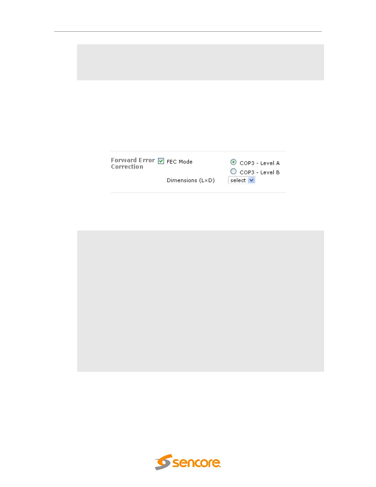
Figure 7.32 - Forward Error Correction Panel for IP Modules
The following parameters are available:
FEC Mode
FEC mechanism can be used to correct errors that occur during
transport.
Choose either one:
• COP3 – Level A: Use FEC Columns only (protects again
burst loss)
• COP3 – Level B: Use both FEC Columns and Rows
(provides additional protection against Random Packet Loss)
A FEC Matrix is generated and transmitted on two separate UDP
ports:
• FEC columns on UDP Port +2, and when using level B:
• FEC Rows on UDP Port +4.
When FEC is enabled, it is important that the UDP ports reserved for
the FEC system is not occupied by other traffic.
Dimensions (LxD)
The FEC matrix, L=Columns, D=Rows; value ranges from 1 to 20.
7.4.1.2 Output Redundancy Related Parameters
The Output Redundancy fields are to be used in a system configuration where two IP modules
or services are configured in a redundancy scenario. Refer to Section 10.4 for further details.