DMG 3200/3100/3000 – User Manual
Page 253 (306)
Input redundancy is managed by the Man Machine Interface (MMI) board which determines when
to switch:
• From one service (Main) to another service (Backup), or
• From one port (Main) to another port (Backup).
However, it is possible that both these services and ports have different content.
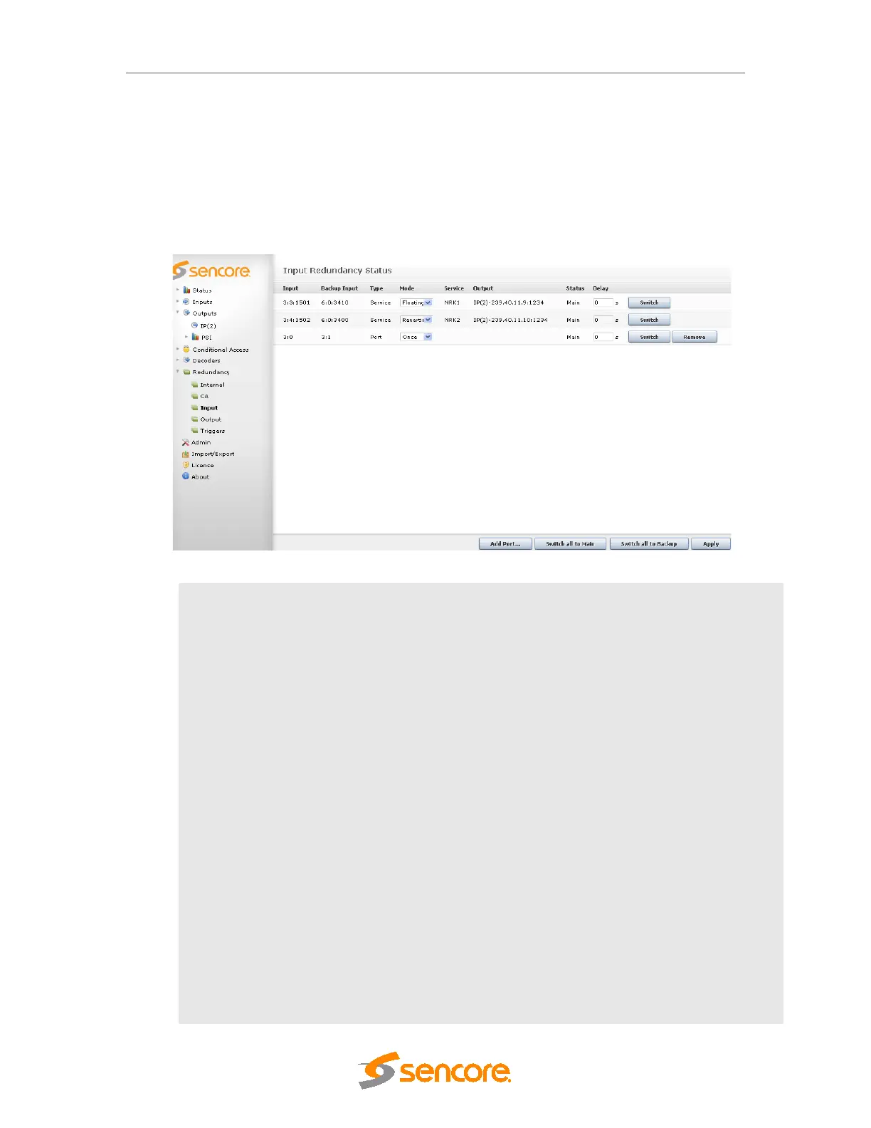
Figure 10.1- Input Redundancy Configuration
Input
Input port or service; the notation is <X:Y:Z> where:
• X – input module’s slot position
• Y – input module’s port
• Z – service SID
Backup Input
Backup input port or service; the notation is <X:Y:Z> where:
• X – input module’s slot position
• Y – input module’s port
• Z – service SID
Type
Type of input redundancy, either Service or Port.
Mode
Displays the switching mode being used.
Service
Outgoing value
Output
Outgoing value
Status
Shows the current redundancy status, either:
Main – inputs are routed from the main input source