DMG 3200/3100/3000 – User Manual
Page 260 (306)
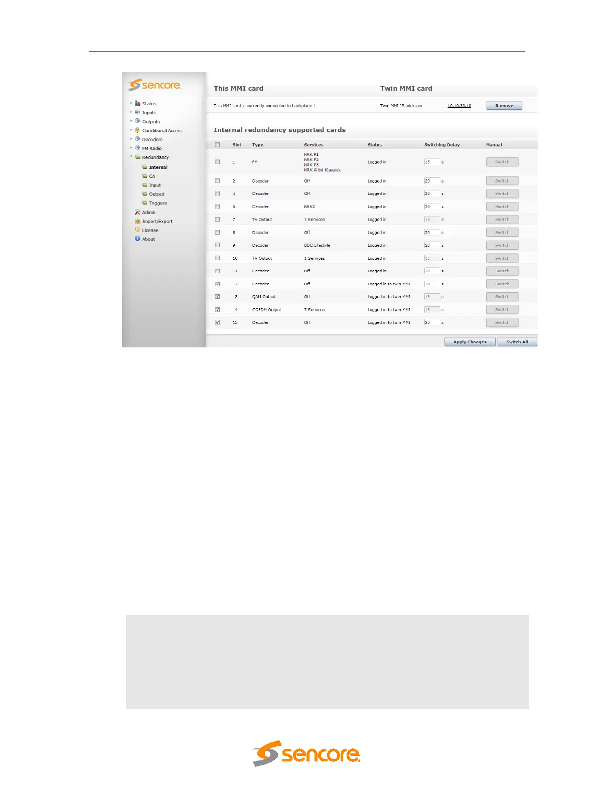
Figure 10.8 - Internal Redundancy
There are three sections on the Internal Redundancy configuration page:
This MMI card – displays the status of the MMI module in the chassis. This section is used as
an indicator for MMI correlation. MMI correlation is needed to get rid of the card missing alarms
on the spare MMI module. The status of the MMI module depends on which backplane it is
logged in to.
Twin MMI card – displays the status of the Twin MMI card linked to this chassis, if there is one.
The IP address of the redundant MMI module is used to notify the internal redundancy GUI
about the module. This other MMI module is referred to as Twin MMI. Once a Twin MMI is
added, both MMI modules will exchange their module list; all other configuration must be done
separately on each MMI module.
Internal redundancy supported cards – displays a list of modules on which internal
redundancy is supported, along with the service name (or number of services for QAM output
modules), status, and switching delay. If internal redundancy is not enabled, the service name
value is off.
An alarm with the message Unable to communicate with TWIN MMI is generated whenever
connection breaks between MMI Input cards.
Enable
The check box must be checked to enable internal redundancy on the
module. Each module can be configured at any time no matter which
backplane it is logged in to.
Slot
The slot in which the module has been installed
Type
The type of module on which internal redundancy is being enabled