Advanced-control timers (TIM1/TIM8/TIM20) RM0440
1140/2126 RM0440 Rev 4
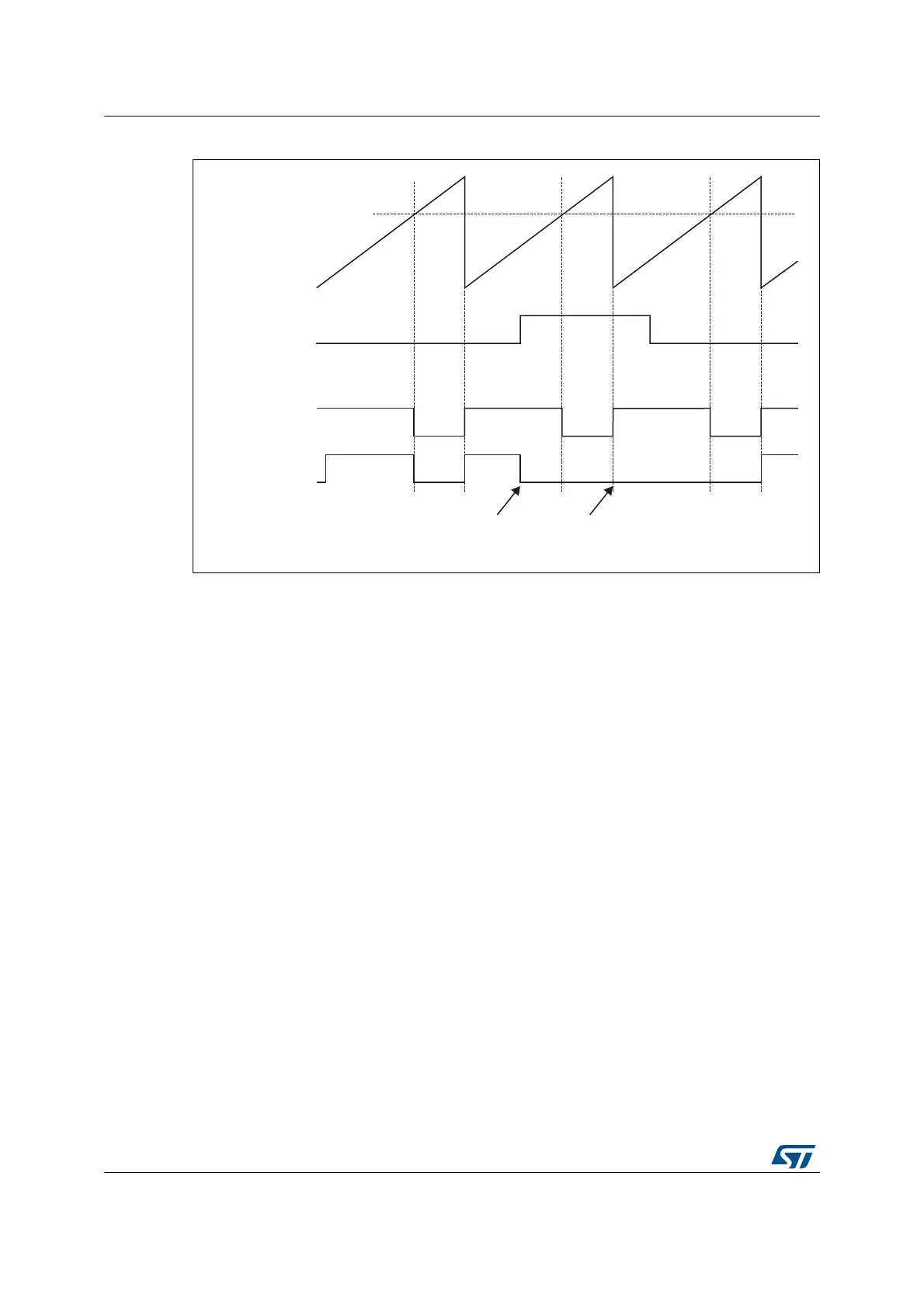
Figure 322. Clearing TIMx tim_ocxref
Note: In case of a PWM with a 100% duty cycle (if CCRx>ARR), then tim_ocxref is enabled again
at the next counter overflow.
28.3.21 6-step PWM generation
When complementary outputs are used on a channel, preload bits are available on the
OCxM, CCxE and CCxNE bits. The preload bits are transferred to the shadow bits at the
COM commutation event. Thus one can program in advance the configuration for the next
step and change the configuration of all the channels at the same time. COM can be
generated by software by setting the COM bit in the TIMx_EGR register or by hardware (on
tim_trgi rising edge).
A flag is set when the COM event occurs (COMIF bit in the TIMx_SR register), which can
generate an interrupt (if the COMIE bit is set in the TIMx_DIER register) or a DMA request
(if the COMDE bit is set in the TIMx_DIER register).
The Figure 323 describes the behavior of the tim_ocx and tim_ocxn outputs when a COM
event occurs, in 3 different examples of programmed configurations.
MSv62342V1
(CCRx)
Counter (CNT)
tim_etrf
tim_ocxref
(OCxCE = ‘0’)
tim_ocxref
(OCxCE = ‘1’)
tim_ocref_clr_int
becomes high
tim_ocref_clr_int
still high
 Loading...


