RM0440 Rev 4 1171/2126
RM0440 Advanced-control timers (TIM1/TIM8/TIM20)
1226
1. Configure the external trigger input circuit by programming the TIMx_SMCR register as
follows:
– ETF = 0000: no filter
– ETPS=00: prescaler disabled
– ETP=0: detection of rising edges on tim_etr_in and ECE=1 to enable the external
clock mode 2.
2. Configure the channel 1 as follows, to detect rising edges on TI:
– IC1F=0000: no filter.
– The capture prescaler is not used for triggering and does not need to be
configured.
– CC1S=01in TIMx_CCMR1 register to select only the input capture source
– CC1P=0 and CC1NP=’0’ in TIMx_CCER register to validate the polarity (and
detect rising edge only).
3. Configure the timer in trigger mode by writing SMS=110 in TIMx_SMCR register. Select
tim_ti1 as the input source by writing TS=00101 in TIMx_SMCR register.
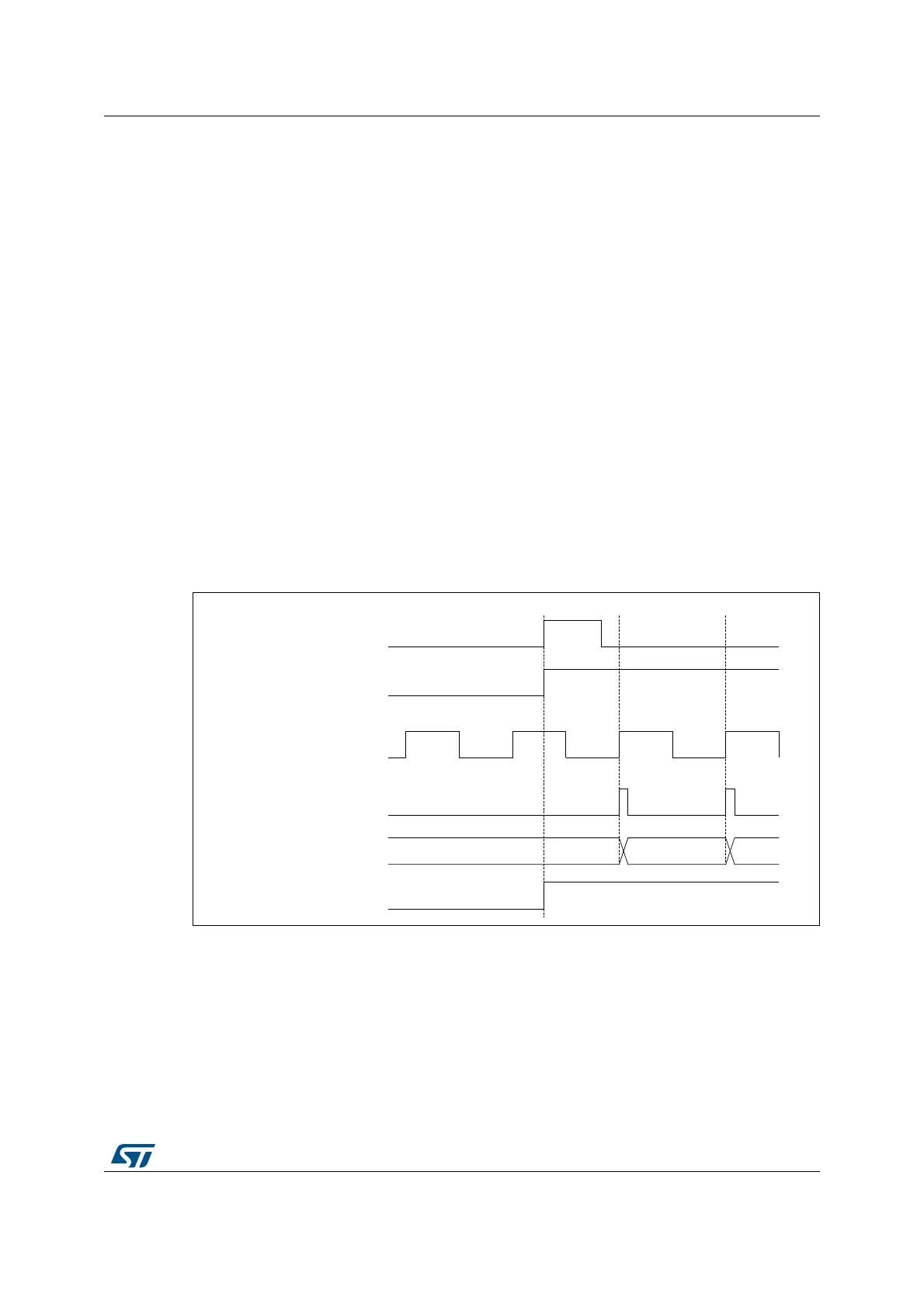
A rising edge on tim_ti1 enables the counter and sets the TIF flag. The counter then counts
on tim_etr_in rising edges.
The delay between the rising edge of the tim_etr_in signal and the actual reset of the
counter is due to the resynchronization circuit on tim_etrp input.
Figure 357. Control circuit in external clock mode 2 + trigger mode
Note: The clock of the slave peripherals (timer, ADC, ...) receiving the tim_trgo or the tim_trgo2
signals must be enabled prior to receive events from the master timer, and the clock
frequency (prescaler) must not be changed on-the-fly while triggers are received from the
master timer.
MSv62364V1
34 35 36
TIF
Counter register
tim_cnt_ck, tim_psc_ck
ETR
CEN
tim_ti1
 Loading...


