Analog-to-digital converters (ADC) RM0440
624/2126 RM0440 Rev 4
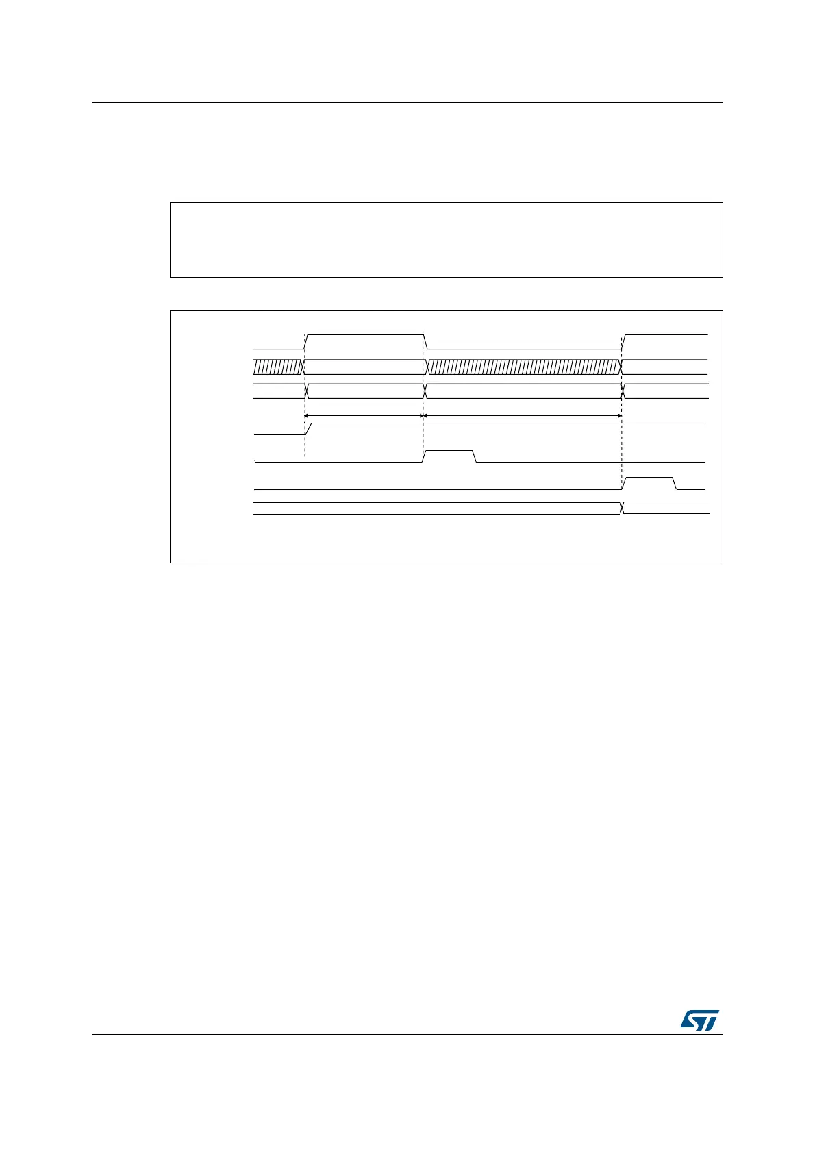
21.4.16 ADC timing
The elapsed time between the start of a conversion and the end of conversion is the sum of
the configured sampling time plus the successive approximation time depending on data
resolution:
Figure 94. Analog to digital conversion time
1. T
SMPL
depends on SMP[2:0].
2. T
SAR
depends on RES[2:0].
21.4.17 Stopping an ongoing conversion (ADSTP, JADSTP)
The software can decide to stop regular conversions ongoing by setting ADSTP=1 and
injected conversions ongoing by setting JADSTP=1.
Stopping conversions will reset the ongoing ADC operation. Then the ADC can be
reconfigured (ex: changing the channel selection or the trigger) ready for a new operation.
Note that it is possible to stop injected conversions while regular conversions are still
operating and vice-versa. This allows, for instance, re-configuration of the injected
conversion sequence and triggers while regular conversions are still operating (and vice-
versa).
When the ADSTP bit is set by software, any ongoing regular conversion is aborted with
partial result discarded (ADC_DR register is not updated with the current conversion).
When the JADSTP bit is set by software, any ongoing injected conversion is aborted with
partial result discarded (ADC_JDRy register is not updated with the current conversion).
The scan sequence is also aborted and reset (meaning that relaunching the ADC would
restart a new sequence).
Once this procedure is complete, bits ADSTP/ADSTART (in case of regular conversion), or
JADSTP/JADSTART (in case of injected conversion) are cleared by hardware and the
software must poll ADSTART (or JADSTART) until the bit is reset before assuming the ADC
is completely stopped.
T
CONV
= T
SMPL
+ T
SAR
= [2.5
|min
+ 12.5
|12bit
] x T
ADC_CLK
T
CONV
= T
SMPL
+ T
SAR
= 83.33 ns
|min
+ 416.67 ns
|12bit
= 500.0 ns (for F
ADC_CLK
= 30 MHz)
Data N-1 Data N
MS30532V1
ADC state
ADSTART
ADC_DR
Analog channel
Internal S/H
EOSMP
EOC
RDY
Set
by S/W
Cleared
by S/W
Set
by H/W
Set
by H/W
Sampling Ch(N)
Converting Ch(N)
Sampling Ch(N+1)
Ch(N+1)
Sample AIN(N+1)
Cleared
by S/W
Hold AIN(N)
Ch(N)
Sample AIN(N)
Indicative timings
SMPL
t
(1)
SAR
t
(2)
 Loading...


