Reset and clock control (RCC) RM0440
282/2126 RM0440 Rev 4
Clock source switching conditions:
• Switching from HSE or HSI16 to PLL with AHB frequency (HCLK) higher than 80 MHz
• Switching from PLL with HCLK higher than 80 MHz to HSE or HSI16
Transition state:
• Set the AHB prescaler HPRE[3:0] bits to divide the system frequency by 2
• Switch system clock to PLL
• Wait for at least 1 µs and then reconfigure AHB prescaler bits to the needed HCLK
frequency
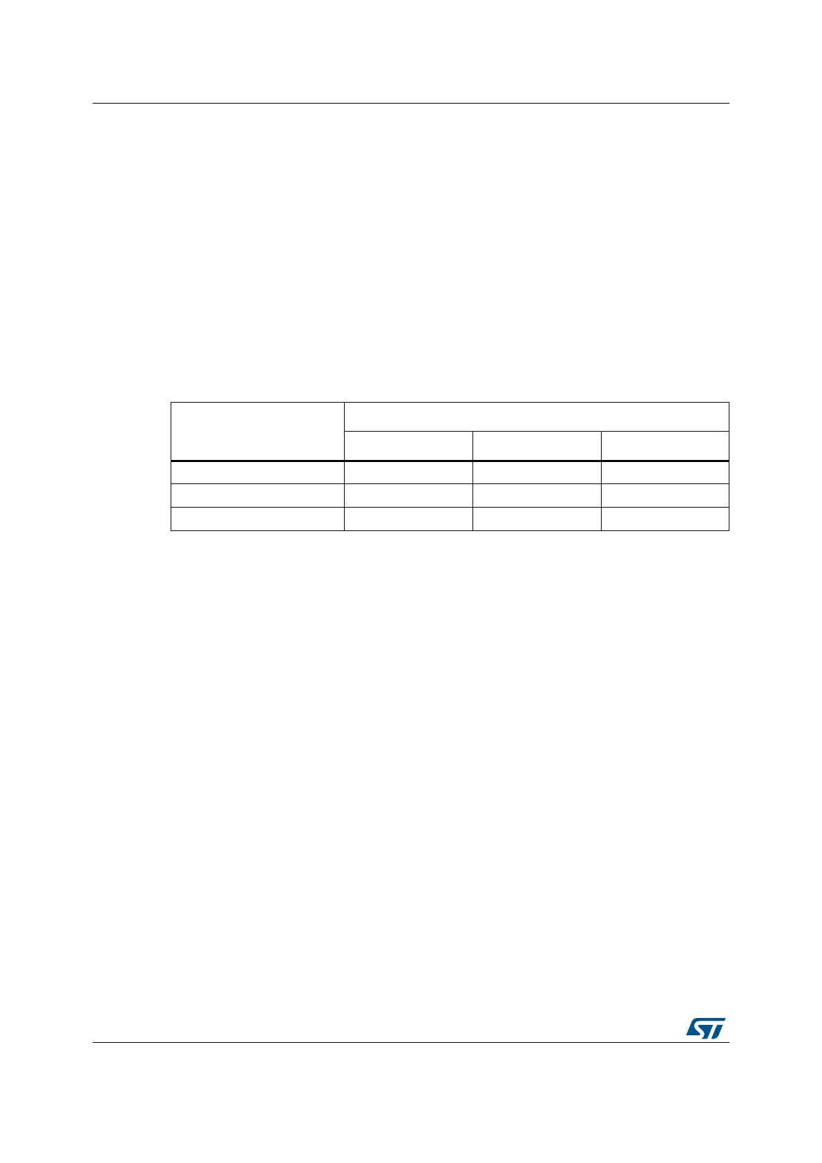
7.2.8 Clock source frequency versus voltage scaling
The following table gives the different clock source frequencies depending on the product
voltage range.
7.2.9 Clock security system (CSS)
Clock Security System can be activated by software. In this case, the clock detector is
enabled after the HSE oscillator startup delay, and disabled when this oscillator is stopped.
If a failure is detected on the HSE clock, the HSE oscillator is automatically disabled, a clock
failure event is sent to the break input of the advanced-control timers (TIM1/TIM8/TIM20
and TIM15/16/17) and to the hrtim_sys_flt, and an interrupt is generated to inform the
software about the failure (Clock Security System Interrupt CSSI), allowing the MCU to
perform rescue operations. The CSSI is linked to the Cortex
®
-M4 with FPU NMI (Non-
Maskable Interrupt) exception vector.
Note: Once the CSS is enabled and if the HSE clock fails, the CSS interrupt occurs and a NMI is
automatically generated. The NMI is executed indefinitely unless the CSS interrupt pending
bit is cleared. As a consequence, in the NMI ISR user must clear the CSS interrupt by
setting the CSSC bit in the Clock interrupt clear register (RCC_CICR).
If the HSE oscillator is used directly or indirectly as the system clock (indirectly means: it is
used as PLL input clock, and the PLL clock is used as system clock), a detected failure
causes a switch of the system clock to the HSI16 oscillator, and the disabling of the HSE
oscillator. If the HSE clock (divided or not) is the clock entry of the PLL used as system clock
when the failure occurs, the PLL is disabled too.
7.2.10 Clock security system on LSE
A Clock Security System on LSE can be activated by software writing the LSECSSON bit in
the Control/status register (RCC_CSR). This bit can be disabled only by a hardware reset or
RTC software reset, or after a failure detection on LSE. LSECSSON must be written after
Table 50. Clock source frequency
Product voltage range
Clock frequency
HSI16 HSE PLL
Range 1 Boost mode 16 MHz 48 MHz 170 MHz
Range 1 normal mode 16 MHz 48 MHz 150 MHz
Range 2 16 MHz 26 MHz 26 MHz