RM0440 Rev 4 621/2126
RM0440 Analog-to-digital converters (ADC)
724
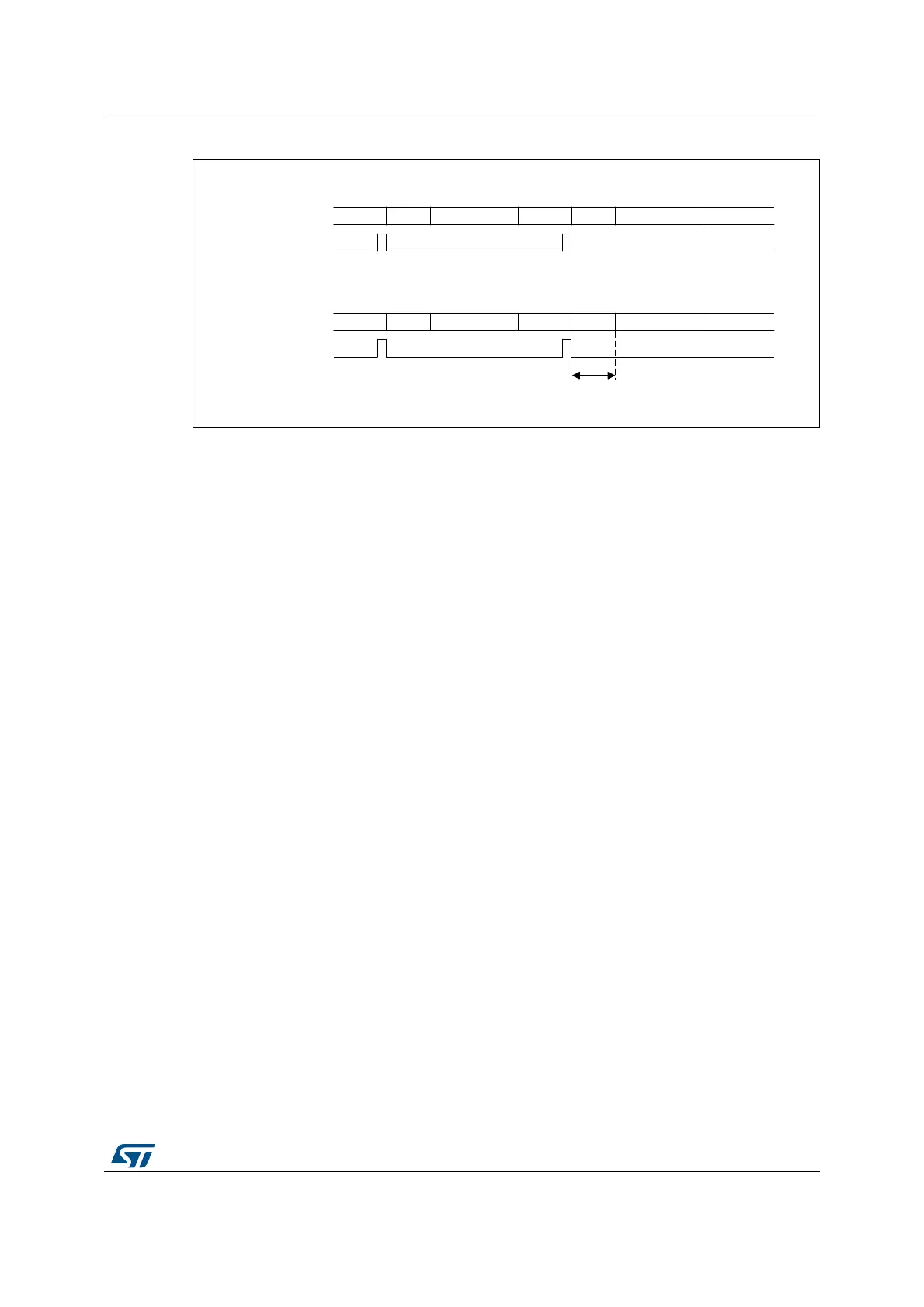
Figure 93. Bulb mode timing diagram
Sampling time control trigger mode
When the SMPTRIG bit is set, the sampling time programmed though SMPx bits is not
applicable. The sampling time is controlled by the trigger signal edge.
When a hardware trigger is selected, each rising edge of the trigger signal starts the
sampling period. A falling edge ends the sampling period and starts the conversion. The
EXTEN[1:0] bits must be set to 01. Hardware triggers with not defined rising and falling
edges (one pulse event) cannot be used in Bulb mode.
When a software trigger is selected, the software trigger is not the ADSTART bit in ADC_CR
but the SWTRIG bit. SWTRIG bit has to be set to start the sampling period, and the
SWTRIG bit has to be cleared to end the sampling period and start the conversion.
EXTEN[1:0] bits must be set to 00.
The maximum sampling time is limited (refer to the ADC characteristics section of the
datasheet).
This mode is neither compatible with the continuous conversion mode, nor with the injected
channel conversion.
When SMPTRIG bit is set, it is not allowed to set BULB bit.
I/O analog switches voltage booster
The I/O analog switches resistance increases when the V
DDA
voltage is too low. This
requires to have the sampling time adapted accordingly (cf datasheet for electrical
characteristics). This resistance can be minimized at low V
DDA
by enabling an internal
voltage booster with BOOSTEN bit in the SYSCFG_CFGR1 register.
SMPPLUS control bit
When a sampling time of 2.5 ADC clock cycles is selected, the total conversion time
becomes 15 cycles in 12-bit mode. If the dual interleaved mode is used (see Section :
Interleaved mode with independent injected), the sampling interval cannot be equal to the
value specified since an even number of cycles is required for the conversion. The
SMPPLUS bit can be used to change the sampling time 2.5 ADC clock cycles into 3.5 ADC
clock cycles. In this way, the total conversion time becomes 16 clock cycles, thus making
possible to interleave every 8 cycles.
MSv46157V2
ADC state
Trigger
Normal (discontinuous) mode
idle
sample
conversion idle conversionsample idle
ADC state
Trigger
BULB (continuous) mode
idle
sample
conversion conversionsample sample
Sampling time programmed in
SMP bits
 Loading...


