RM0440 Rev 4 679/2126
RM0440 Analog-to-digital converters (ADC)
724
DMA requests in dual ADC mode
In all dual ADC modes, it is possible to use two DMA channels (one for the master, one for
the slave) to transfer the data, like in single mode (refer to Figure 150: DMA Requests in
regular simultaneous mode when MDMA=0b00).
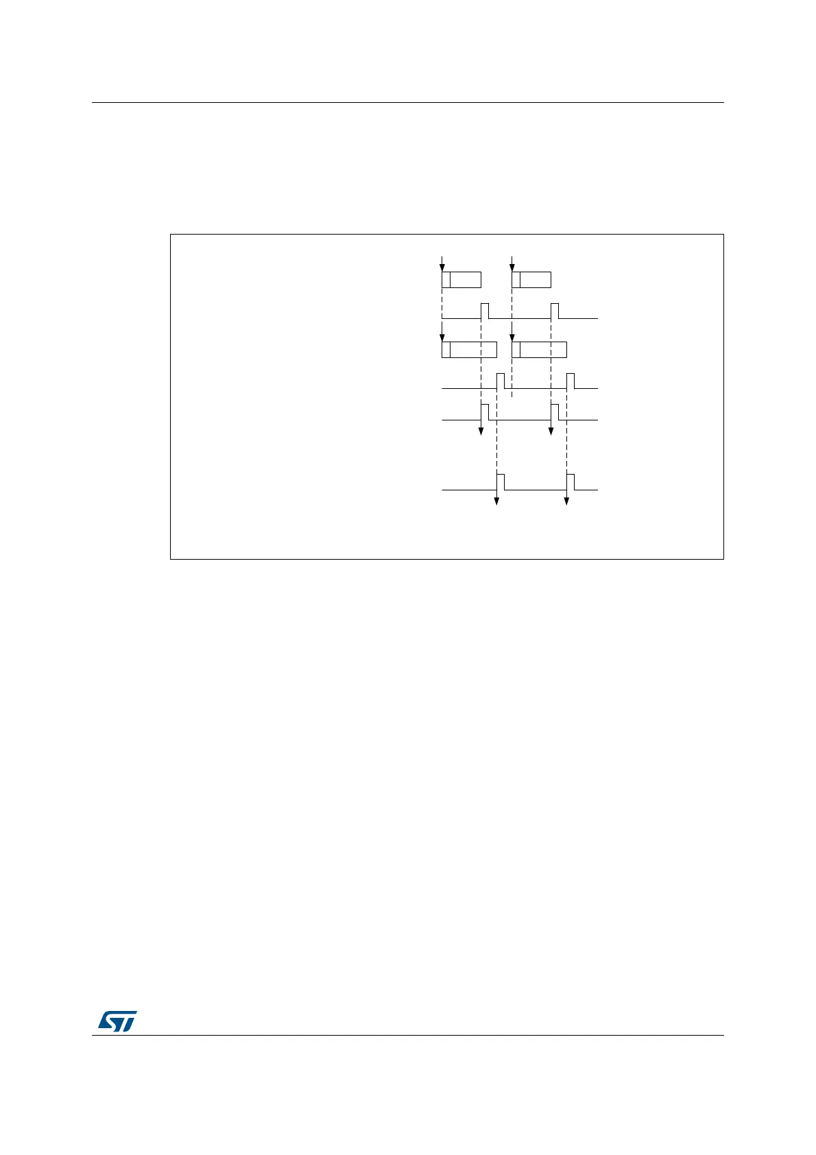
Figure 150. DMA Requests in regular simultaneous mode when MDMA=0b00
In simultaneous regular and interleaved modes, it is also possible to save one DMA channel
and transfer both data using a single DMA channel. For this MDMA bits must be configured
in the ADCx_CCR register:
• MDMA=0b10: A single DMA request is generated each time both master and slave
EOC events have occurred. At that time, two data items are available and the 32-bit
register ADCx_CDR contains the two half-words representing two ADC-converted data
items. The slave ADC data take the upper half-word and the master ADC data take the
lower half-word.
This mode is used in interleaved mode and in regular simultaneous mode when
resolution is 10-bit or 12-bit.
Example:
Interleaved dual mode: a DMA request is generated each time 2 data items are
available:
1st DMA request: ADCx_CDR[31:0] = SLV_ADC_DR[15:0] | MST_ADC_DR[15:0]
2nd DMA request: ADCx_CDR[31:0] = SLV_ADC_DR[15:0] |
MST_ADC_DR[15:0]
MSv31032V2
CH1ADC Master regular
CH2
Trigger Trigger
CH2
CH1
Configuration where each sequence contains only one conversion
ADC Master EOC
ADC Slave regular
ADC Slave EOC
DMA request from ADC Master
DMA request from ADC Slave
DMA reads Master
ADC_DR
DMA reads Mater
ADC_DR
DMA reads Slave
ADC_DR
DMA reads Slave
ADC_DR