Analog-to-digital converters (ADC) RM0440
682/2126 RM0440 Rev 4
The uncalibrated internal temperature sensor is more suited for applications that detect
temperature variations instead of absolute temperatures. To improve the accuracy of the
temperature sensor measurement, calibration values are stored in system memory for each
device by ST during production.
During the manufacturing process, the calibration data of the temperature sensor and the
internal voltage reference are stored in the system memory area. The user application can
then read them and use them to improve the accuracy of the temperature sensor or the
internal reference (refer to the datasheet for additional information).
The temperature sensor is internally connected to the ADC input channel which is used to
convert the sensor’s output voltage to a digital value. Refer to the electrical characteristics
section of the device datasheet for the sampling time value to be applied when converting
the internal temperature sensor.
When not in use, the sensor can be put in power-down mode.
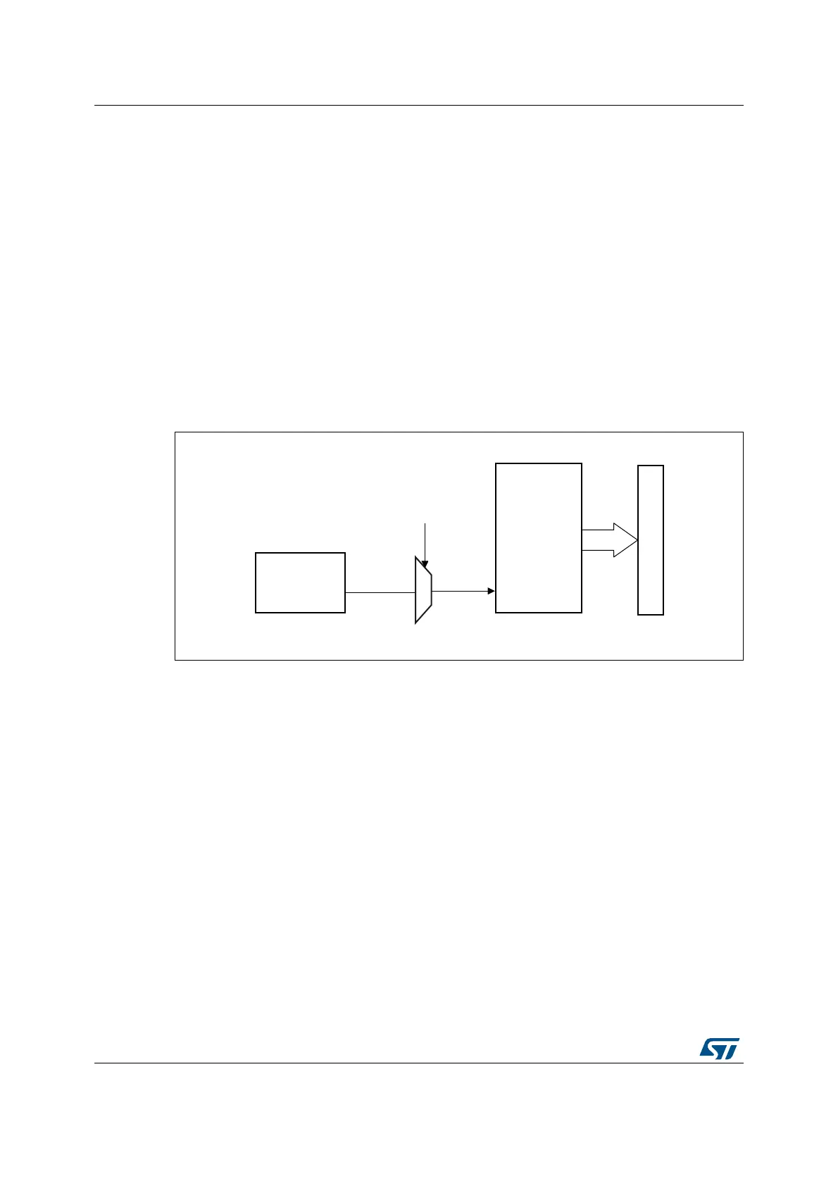
Figure 153 shows the block diagram of the temperature sensor.
Figure 153. Temperature sensor channel block diagram
Reading the temperature
To use the sensor:
1. Select the ADC input channels that is connected to V
TS
.
2. Program with the appropriate sampling time (refer to electrical characteristics section of
the device datasheet).
3. Set the VSENSESEL bit in the ADCx_CCR register to wake up the temperature sensor
from power-down mode.
4. Start the ADC conversion.
5. Read the resulting V
TS
data in the ADC data register.
6. Calculate the actual temperature using the following formula:
MSv46150V2
V
TS
VSENSESEL
control bit
ADCx
ADC input
Address/data bus
Temperature
sensor
Converted
data
Temperature in °C()
TS_CAL2_TEMP TS_CAL1_TEMP–
TS_CAL2 TS_CAL1–
--------------------------------------------------------------------------------------------------
TS_DATA TS_CAL1–()30 °C+×=