Serial audio interface (SAI) RM0440
1808/2126 RM0440 Rev 4
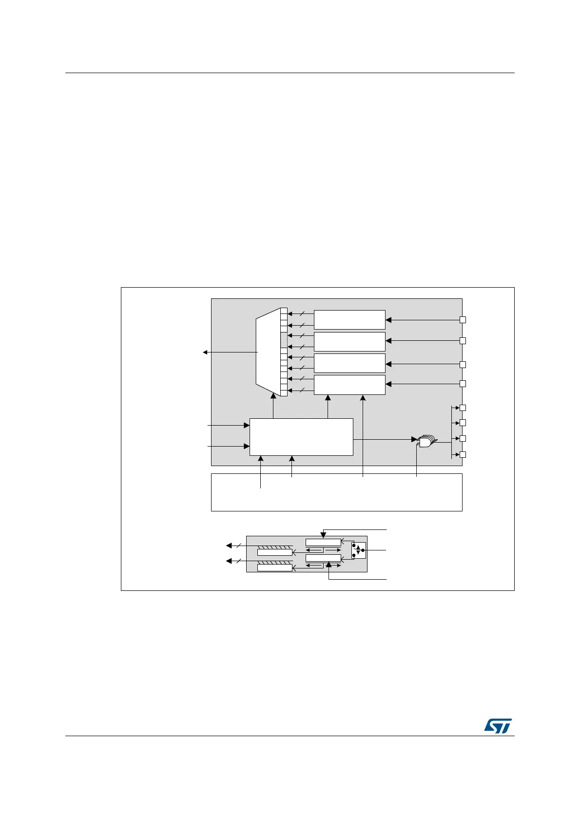
The data processing sequence into the PDM is the following:
1. The PDM interface builds the bitstream clock from the bit clock received from the TDM
interface of SAI_A.
2. The bitstream data received from the microphones (SAI_D[n]) are de-interleaved and
go through a 7-bit delay line in order to fine-tune the delay of each microphone with the
accuracy of the bitstream clock.
3. The shift registers translate each serial bitstream into bytes.
4. The last operation consists in shifting-out the resulting bytes to SAI_A via the serial
data line of the TDM interface.
Figure 616 hereafter shows the block diagram of PDM interface, with a detailed view of a
de-interleaver.
Note: The PDM interface does not embed the decimation filter required to build-up the PCM audio
samples from the bitstream. It is up to the application software to perform this operation.
Figure 616. Detailed PDM interface block diagram
1. n refers to the number of data lines and p to the number of microphone pairs.
The PDM interface can be enabled through the PDMEN bit in SAI_PDMCR register.
However the PDM interface must be enabled prior to enabling SAI_A block.
To reduce the memory footprint, the user can select the amount of microphones the
application needs. This can be done through MICNBR[1:0] bits. It is possible to select
between 2,4,6 or 8 microphones. For example, if the application is using 3 microphones, the
user has to select 4.
MSv35468V4
De-Interleaver1
De-Interleaver2
De-Interleaver3
De-Interleaver4
To saia_sd_in
Control
Logic
PDM_IF
8
8
8
8
8
8
8
8
1 2 3 4 5 6 7 8 61626364
LatchReg
From saia_fs_out
From saia_sck_out
SAI register interface
pdm_ck
SAI_D[n]
delay line
shift reg
8
delay line
shift reg
8
De-Interleaver n
DLYMpL
DLYMpR
PDMEN
MICNBR CKEN[4:1]
SAI_D1
SAI_D2
SAI_D3
SAI_D4
SAI_CK1
SAI_CK2
SAI_CK3
SAI_CK4
DLYM[4:1]L,
DLYM[4:1]R
 Loading...


