General-purpose timers (TIM2/TIM3/TIM4/TIM5) RM0440
1298/2126 RM0440 Rev 4
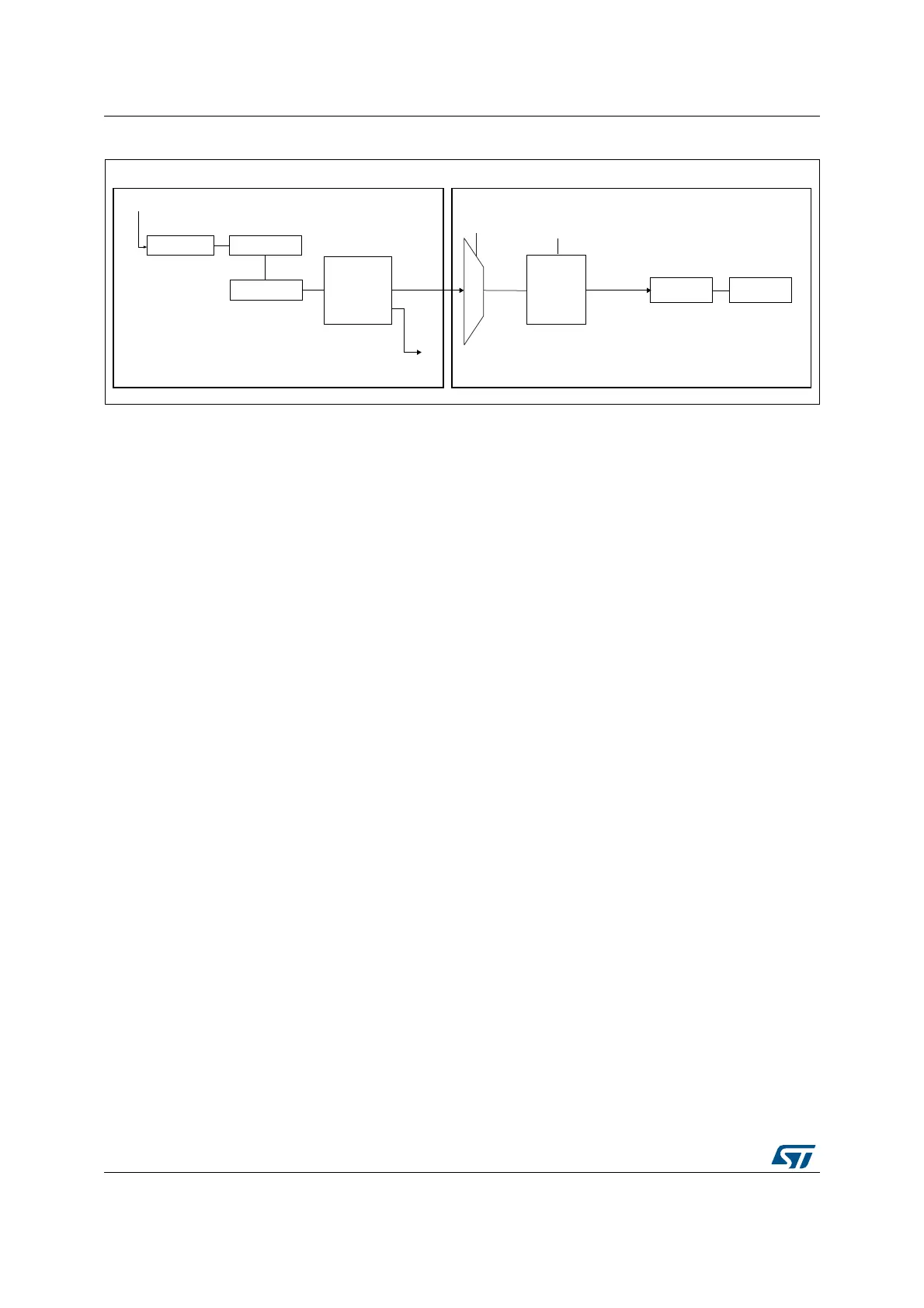
Figure 433. Master/slave connection example with 1 channel only timers
Note: The timers with one channel only (see Figure 433) do not feature a master mode. However,
the tim_oc1 output signal can serve as trigger for slave timer (see TIMx internal trigger
connection table in Section 29.4.2: TIM2/TIM3/TIM4/TIM5 pins and internal signals).
The tim_oc1 signal pulse width must be programmed to be at least 2 clock cycles of the
destination timer, to make sure the slave timer will detect the trigger.
For instance, if the destination timer tim_ker_ck clock is 4 times slower than the source
timer, the OC1 pulse width must be 8 clock cycles.
Using one timer as prescaler for another timer
For example, TIM_mstr can be configured to act as a prescaler for TIM_slv. Refer to
Figure 432. To do this:
1. Configure TIM_mstr in master mode so that it outputs a periodic trigger signal on each
update event UEV. If MMS=010 is written in the TIM_mstr_CR2 register, a rising edge
is output on tim_trgo each time an update event is generated.
2. To connect the tim_trgo output of TIM_mstr to TIM_slv, TIM_slv must be configured in
slave mode using ITR2 as internal trigger. This is selected through the TS bits in the
TIM_slv_SMCR register (writing TS=00010).
3. Then the slave mode controller must be put in external clock mode 1 (write SMS=111 in
the TIM_slv_SMCR register). This causes TIM_slv to be clocked by the rising edge of
the periodic TIM_mstr trigger signal (which correspond to the TIM_mstr counter
overflow).
4. Finally both timers must be enabled by setting their respective CEN bits (TIMx_CR1
register).
Note: If tim_ocx is selected on TIM_mstr as the trigger output (MMS=1xx), its rising edge is used
to clock the counter of TIM_slv.
Using one timer to enable another timer
In this example, we control the enable of TIM_slv with the output compare 1 of TIM_mstr.
Refer to Figure 432 for connections. TIM_slv counts on the divided internal clock only when
tim_oc1ref of TIM_mstr is high. Both counter clock frequencies are divided by 3 by the
prescaler compared to tim_ker_ck (f
tim_cnt_ck
= f
tim_ker_ck
/3).
MSv65225V1
Compare 1
Output
control
Slave
mode
control
CounterPrescaler
CK_PSCtim_itrtim_oc1
SMS
TS
Input
trigger
selection
TIM_mstr TIM_slv
CounterPrescaler
Clock
TIM_CH1
 Loading...


