Universal synchronous/asynchronous receiver transmitter (USART/UART) RM0440
1624/2126 RM0440 Rev 4
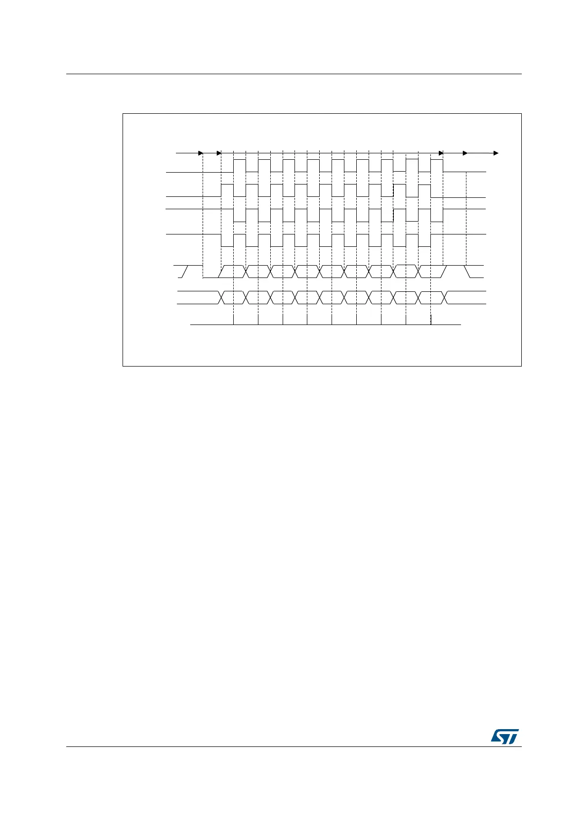
Figure 544. USART data clock timing diagram in synchronous master mode
(M bits = 01)
Slave mode
The synchronous slave mode is selected by programming the SLVEN bit in the
USART_CR2 register to ‘1’. In synchronous slave mode, the following bits must be kept
cleared:
• LINEN and CLKEN bits in the USART_CR2 register,
• SCEN, HDSEL and IREN bits in the USART_CR3 register.
In this mode, the USART can be used to control bidirectional synchronous serial
communications in slave mode. The SCLK pin is the input of the USART in slave mode.
Note: When the peripheral is used in SPI slave mode, the frequency of peripheral clock source
(usart_ker_ck_pres) must be greater than 3 times the CK input frequency.
The CPOL bit and the CPHA bit in the USART_CR2 register are used to select the clock
polarity and the phase of the external clock, respectively (see Figure 545).
An underrun error flag is available in slave transmission mode. This flag is set when the first
clock pulse for data transmission appears while the software has not yet loaded any value to
USART_TDR.
The slave supports the hardware and software NSS management.
MSv34710V1
0 1 2 3 4 5 6 8
0 1 2 3 4 5 6 8
*
*
*
*
MSB
MSB
LSB
LSBStart
Start Stop
Idle or
preceding
transmission
Idle or next
transmission
*
*LBCL bit controls last data pulse
Capture
strobe
Data on RX
(from slave)
Data on TX
(from master)
Clock (CPOL=1,
CPHA=1)
Clock (CPOL=1,
CPHA=0)
Clock (CPOL=0,
CPHA=1)
Clock (CPOL=0,
CPHA=0)
Stop
M bits =01 (9 data bits)
7
7
 Loading...


