RM0440 Rev 4 1387/2126
RM0440 General-purpose timers (TIM15/TIM16/TIM17)
1445
Slave mode: Trigger mode
The counter can start in response to an event on a selected input.
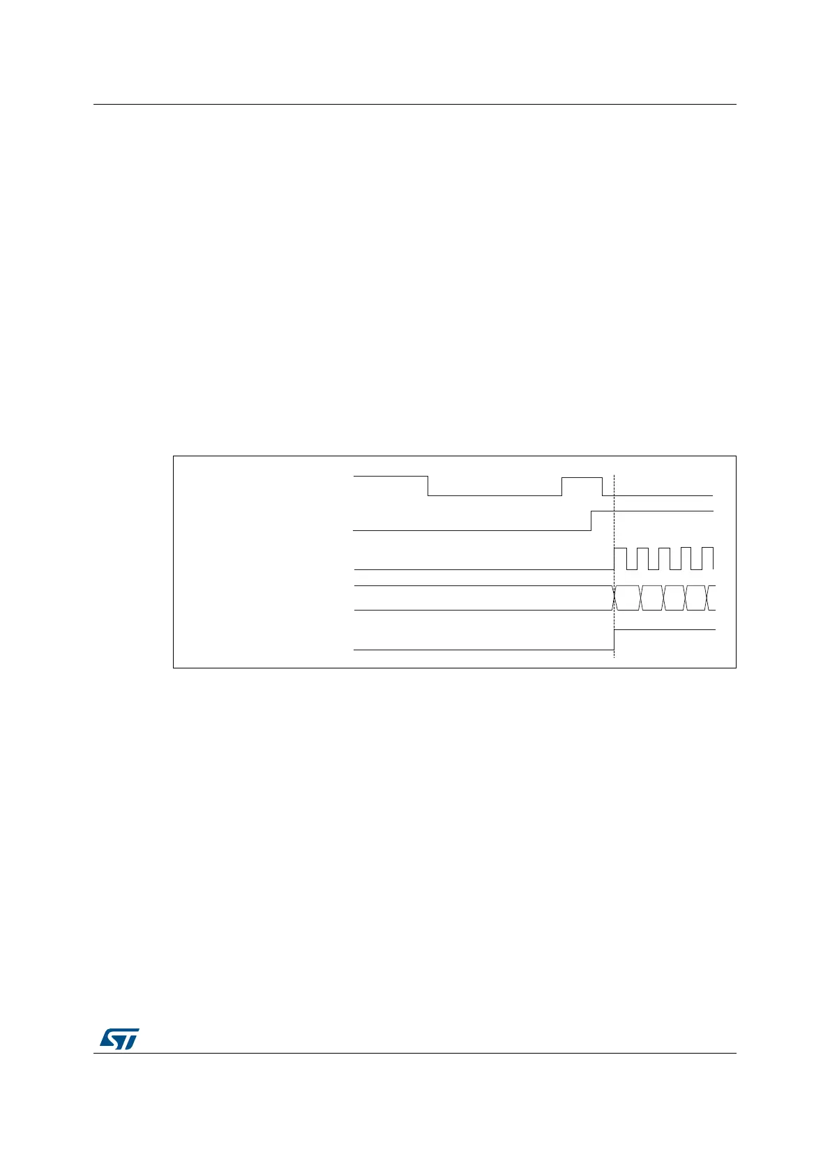
In the following example, the upcounter starts in response to a rising edge on tim_ti2 input:
1. Configure the channel 2 to detect rising edges on tim_ti2. Configure the input filter
duration (in this example, we do not need any filter, so we keep IC2F=0000). The
capture prescaler is not used for triggering, so it does not need to be configured. The
CC2S bits are configured to select the input capture source only, CC2S=01 in
TIMx_CCMR1 register. Write CC2P=’1’ and CC2NP=’0’ in the TIMx_CCER register to
validate the polarity (and detect low level only).
2. Configure the timer in trigger mode by writing SMS=110 in the TIMx_SMCR register.
Select tim_ti2 as the input source by writing TS=00110 in the TIMx_SMCR register.
When a rising edge occurs on tim_ti2, the counter starts counting on the internal clock and
the TIF flag is set.
The delay between the rising edge on tim_ti2 and the actual start of the counter is due to the
resynchronization circuit on tim_ti2 input.
Figure 478. Control circuit in trigger mode
Slave mode selection preload for run-time encoder mode update
The SMS[3:0] bit can be preloaded. This is enabled by setting the SMSPE enable bit in the
TIMx_SMCR register. The trigger for the transfer from SMS[3:0] preload to active value is
the update event (UEV) occurring when the counter overflows.
30.4.23 Slave mode – combined reset + trigger mode (TIM15 only)
In this case, a rising edge of the selected trigger input (tim_trgi) reinitializes the counter,
generates an update of the registers, and starts the counter.
This mode is used for one-pulse mode.
30.4.24 Slave mode – combined reset + gated mode (TIM15 only)
The counter clock is enabled when the trigger input (tim_trgi) is high. The counter stops and
is reset) as soon as the trigger becomes low. Both start and stop of the counter are
controlled.
This mode allows to detect out-of-range PWM signal (duty cycle exceeding a maximum
expected value).
MSv62363V1
37
Counter register
38
34
35 36
TIF
tim_ti2
CEN
tim_cnt_ck, tim_psc_ck
 Loading...


