Reset and clock control (RCC) RM0440
286/2126 RM0440 Rev 4
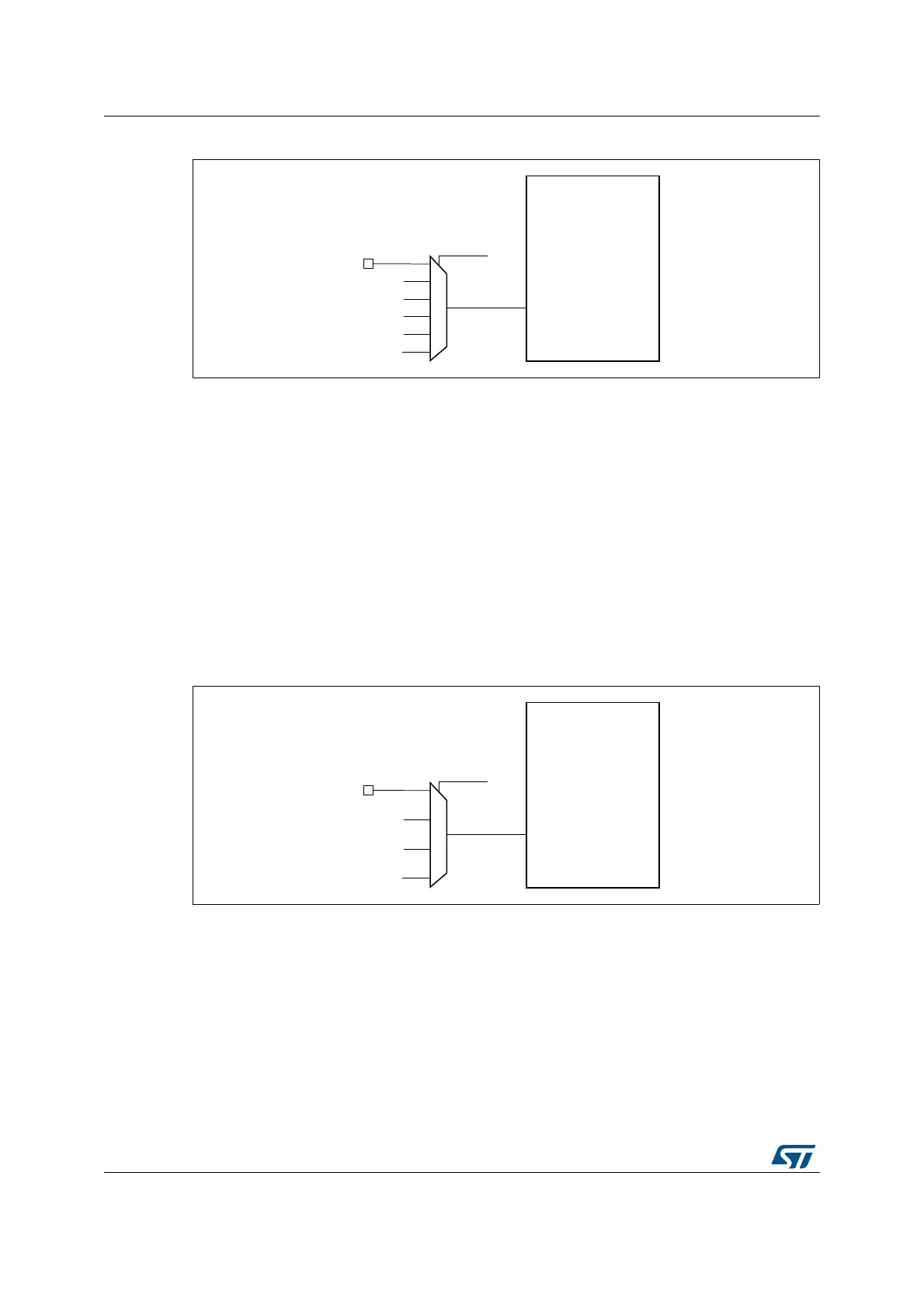
Figure 21. Frequency measurement with TIM17 in capture mode
The input capture channel of the Timer 17 can be a GPIO line or an internal clock of the
MCU.
The possibilities are the following ones:
• TIM17 Channel1 is connected to the GPIO. Refer to the alternate function mapping in
the device datasheets.
• TIM17 Channel1 is connected to the RTC wakeup interrupt. In this case the RTC
interrupt should be enabled.
• TIM17 Channel1 is connected to the HSE/32 Clock.
• TIM17 Channel1 is connected to the microcontroller clock output (MCO), this selection
is controlled by the MCOSEL[3:0] bits of the Clock configuration register (RCC_CFGR).
• TIM17 Channel1 is connected to the LSE Clock.
• TIM17 Channel1 is connected to the LSI Clock.
Figure 22. Frequency measurement with TIM5 in capture mode
The input capture channel of the Timer 5 can be a GPIO line or an internal clock of the
MCU.
The possibilities are the following ones:
• TIM5 Channel1 is connected to the GPIO. Refer to the alternate function mapping in
the device datasheets.
• TIM5 Channel1 is connected to the LSI Clock.
• TIM5 Channel1 is connected to the LSE Clock.
• TIM5 Channel1 is connected to the RTC wakeup interrupt signal. In this case the RTC
interrupt should be enabled.
MSv45849V1
TIM 17
TI1
TI1SEL in
TIM17_TISEL
GPIO
HSE/32
RTC wakeup interrupt
MCO
LSE
LSI
MSv45853V1
TIM 5
TI1
TI1SEL in
TIM5_TISEL
GPIO
RTC wakeup interrupt
LSE
LSI
 Loading...


