RM0440 Rev 4 853/2126
RM0440 High-resolution timer (HRTIM)
1083
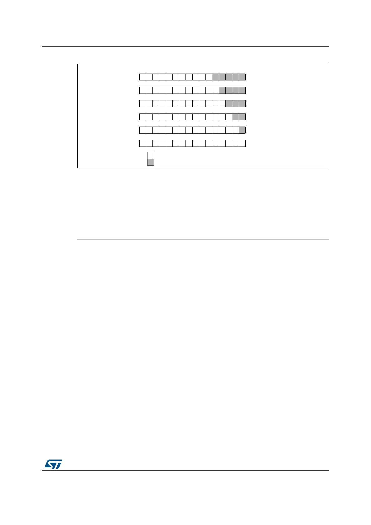
Figure 183. Counter and capture register format vs clock prescaling factor
Initialization
At start-up, it is mandatory to initialize first the prescaler bitfields before writing the compare
and period registers. Once the timer is enabled (MCEN or TxCEN bit set in the
HRTIM_MCR register), the prescaler cannot be modified.
When multiple timers are enabled, the prescalers are synchronized with the prescaler of the
timer that was started first.
Warning: It is possible to have different prescaling ratios in the master
and TIMA..E timers only if the counter and output behavior
does not depend on other timers’ information and signals. It
is mandatory to configure identical prescaling ratios in these
timers when one of the following events is propagated from
one timing unit (or master timer) to another: output set/reset
event, counter reset event, update event, external event filter
or capture triggers. Prescaler factors not equal yield to
unpredictable results.
Deadtime generator clock
The deadtime prescaler is supplied by (f
HRTIM
x 8) / 2
(DTPRSC[2:0])
, programmed with
DTPRSC[2:0] bits in the HRTIM_DTxR register.
t
DTG
ranges from 735 ps to 94.1 ns for f
HRTIM
= 170 MHz.
Chopper stage clock
The chopper stage clock source f
CHPFRQ
is derived from f
HRTIM
with a division factor
ranging from 16 to 256, so that 664.06 kHz ≤ f
CHPFRQ
≤ 10.625 MHz for f
HRTIM
=170MHz.
t
1STPW
is the length of the initial pulse in chopper mode, programmed with the STRPW[3:0]
bits in the HRTIM_CHPxR register, as follows:
t
1STPW
= (STRPW[3:0]+1) x 16 x t
HRTIM
.
It uses f
HRTIM
/ 16 as clock source (10.625 MHz for f
HRTIM
= 170 MHz).
MS32257V1
Prescalingb15
Significant bit: read returns effective value
Not significant bit: read returns 0
b0
1
2
4
8
16
32
 Loading...


